
A brake is a device by means of which artificial frictional resistance is applied to a moving machine member, in order to retard or stop the motion of a machine. In the process of performing this function, the brake absorbs either the kinetic energy of the moving member or potential energy given up by objects being lowered by hoists, elevators, etc. In the previous articles, we discussed how we can calculate the energy absorbed by a brake and Heat Dissipation during Braking. We also discussed the different types of Brakes in the previous article. Let us discuss the Internal Expanding Brake in detail.

As we mentioned above that the brake is used to retard or stop the motion of a machine. This action is called Braking. In the process of braking, the brake absorbs either the kinetic energy of the moving member or potential energy given up by objects being lowered by hoists, elevators, etc. The energy absorbed by brakes is dissipated in the form of heat. This heat is dissipated in the surrounding air (or water which is circulated through the passages in the brake drum) so that excessive heating of the brake lining does not take place.
The design or capacity of a brake depends upon the following factors:
- The unit pressure between the braking surfaces
- The coefficient of friction between the braking surfaces
- The peripheral velocity of the brake drum
- The projected area of the friction surfaces
- The ability of the brake to dissipate heat is equivalent to the energy being absorbed.
The major functional difference between a clutch and a brake is that a clutch is used to keep the driving and driven member moving together, whereas brakes are used to stop a moving member or to control its speed.
We also solved an example problem to stop A vehicle of mass 1200 kg moving down the hill at a slope of 1:5. by finding how much amount of Braking Torque is required to stop the vehicle in the previous article.
Internal Expanding Brake
An internal expanding brake consists of two shoes S1 and S2 as shown in the following figure. The outer surface of the shoes is lined with some friction material (usually with Ferodo) to increase the coefficient of friction and to prevent the wearing away of the metal. Each shoe is pivoted at one end about a fixed fulcrum O1 and O2 and made to contact a cam at the other end.

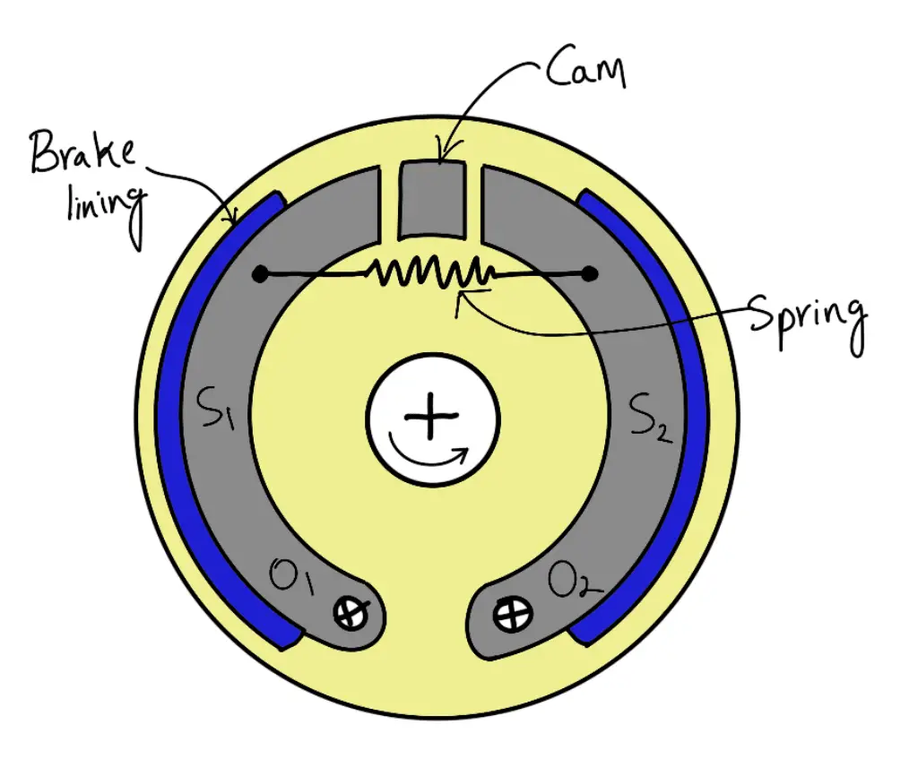
When the cam rotates, the shoes are pushed outwards against the rim of the drum. The friction between the shoes and the drum produces the braking torque and hence reduces the speed of the drum. The shoes are normally held in an off position by a spring as shown in the above figure. The drum encloses the entire mechanism to keep out dust and moisture. This type of brake is commonly used in motor cars and light trucks.
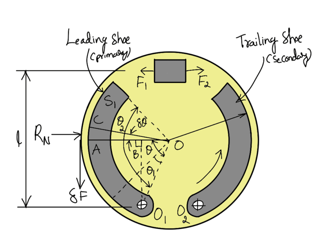
We shall now consider the forces acting on such a brake when the drum rotates in the anticlockwise direction as shown in the following figure. It may be noted that for the anticlockwise direction, the left-hand shoe is known as the leading or primary shoe while the right-hand shoe is known as the trailing or secondary shoe.

Let
r = Internal radius of the wheel rim.
b = Width of the brake lining.
P1 = Maximum intensity of normal pressure
PN = Normal pressure,
F1 = Force exerted by the cam on the leading shoe
F2 = Force exerted by the cam on the trailing shoe.
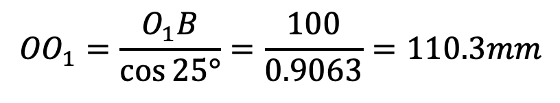
Consider a small element of the brake lining AC subtending an angle δθ at the center. Let OA make an angle θ with OO1 as shown in the above figure. It is assumed that the pressure distribution on the shoe is nearly uniform, however the friction lining wears out more at the free end. Since the shoe turns about O1, therefore the rate of wear of the shoe lining at A will be proportional to the radial displacement of that point. The rate of wear of the shoe lining varies directly as the perpendicular distance from O1 to OA, i.e. O1B. From the geometry of the figure,
O1B = OO1 sin θ
and normal pressure at A, pN ∝ sinθ or pN = p1 sinθ
∴ Normal force acting on the element,
δRN = Normal pressure × Area of the element
δRN = pN (b . r . δθ) = p1 sinθ (b . r . δθ)
and braking or friction force on the element,
δF = μ . δRN = μ p1 sinθ (b . r . δθ)
∴ Braking torque due to the element about O,
δTB = δF . r = μ p1 sinθ (b . r . δθ) r = μ p1 br2 (sinθ . δθ)
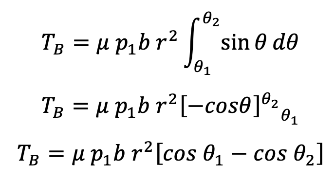
and total braking torque of about O for the whole of one shoe,

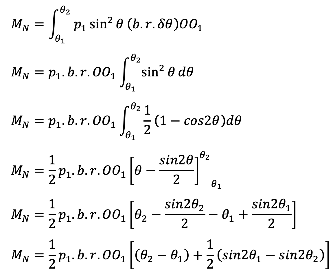
Moment of normal force δRN of the element about the fulcrum O1,
δMN = δRN × O1B = δRN (OO1 sin θ)
δMN = p1 sinθ (b . r . δθ) (OO1 sin θ)
δMN = p1 sin2 θ (b . r . δθ)OO1
Total moment of normal forces about the fulcrum O1,

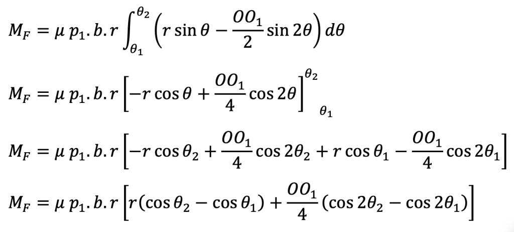
Moment of frictional force δF about the fulcrum O1,
δMF = δF × AB = δF(r–OO1 cos θ)
δMF = μ . p1 sinθ (b . r . δθ)(r–OO1 cos θ)
δMF = μ . p1 . b . r (r sin θ – OO1 sin θ cos θ)δθ
δMF = μ . p1 . b . r (r sin θ – (OO1/2) sin 2θ)δθ
∴ Total moment of frictional force about the fulcrum O1,

Now for the leading shoe, taking moments about the fulcrum O1,
F1 × l = MN – MF
and for trailing shoe, taking moments about the fulcrum O2,
F2 × l = MN + MF
Note that If MF > MN, then the brake becomes self-locking.
How to calculate the braking torque required to Stop the Vehicle with an Internal Expanding Brake?
As shown in the following arrangement of two brake shoes that act on the internal surface of a cylindrical brake drum. The braking force F1 and F2 are applied as shown and each shoe pivots on its fulcrum O1 and O2. The width of the brake lining is 35 mm. The intensity of pressure at any point A is 0.4 sin θ N/mm2, where θ is measured as shown from either pivot. The coefficient of friction is 0.4. Determine the braking torque and the magnitude of the forces F1 and F2.
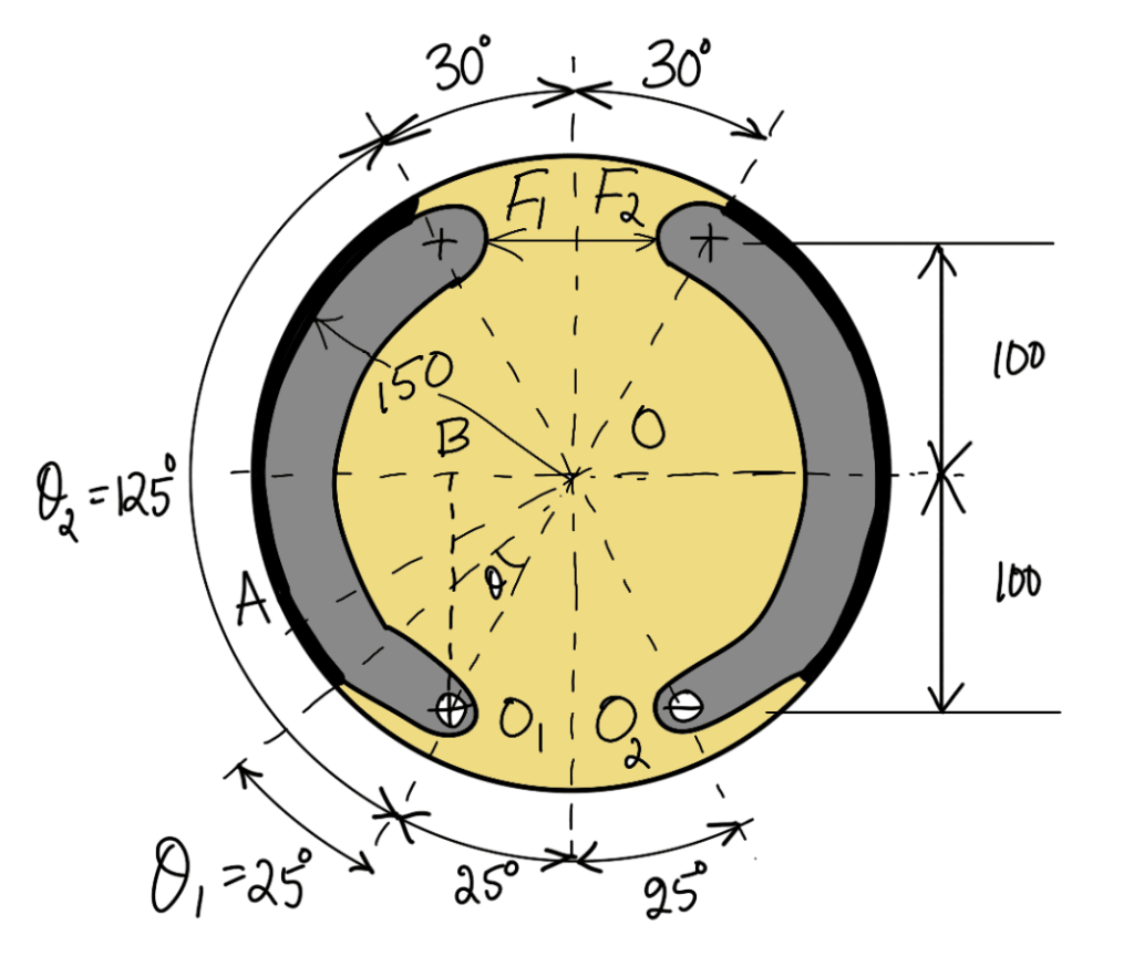

(All dimensions are in mm)
Answer:
Given:
Width of the Brake Lining b = 35mm
Coefficient of friction μ = 0.4
The radius of the drum r = 150mm
Length l = 200mm
θ1 = 25°
θ2 = 125°
Since the intensity of normal pressure at any point is 0.4 sin θ N/mm2, therefore the maximum intensity of normal pressure,
p1 = 0.4 N/mm2
We know that the braking torque for one shoe,
= μ . p1 . b . r2 (cos θ1 – cos θ2)
= 0.4 × 0.4 × 35 (150)2 (cos 25° – cos 125°)
= 126000 (0.9063 + 0.5736)
= 186470 N-mm
∴ Total braking torque for two shoes,
TB = 2 × 186470
TB = 372940N-mm
The total Braking torque is 372940N-mm.
Magnitude of the forces F1 and F2
From the geometry of the figure, we find that

θ1 = 25° = 25 × π/180 = 0.436rad
θ2 = 125°= 125 × π/180 = 2.18rad
We know that the total moment of normal forces about the fulcrum O1,
MN = ½ p1 . b .r OO1 [ (θ2 – θ1 ) + ½ (sin 2θ1 − sin 2θ2 )]
MN = ½ × 0.4 × 35 × 150 × 110.3 [(2.18 – 0.436) + ½ (sin 50°–sin 250°)]
MN = 300754 N-mm
and total moment of friction force about the fulcrum O1,
MF = μ . p1 . b .r [r (cos θ1 – cos θ2 ) + (OO1 /4) (cos 2θ2 − cos 2θ1 )]
MF = 0.4 × 0.4 × 35 × 150 [ 150 (cos 25° – cos 125°) + (110.3/4) (cos 250° – cos 50°)]
MF = 163800 N-mm
For the leading shoe, taking moments about the fulcrum O1,
F1 × l = MN – MF
F1 × 200 = 300754–163800
F1 × 200 =136954
F1 = 136954/200
F1 = 685N
For the trailing shoe, taking moments about the fulcrum O2,
F2 × l = MN + MF
F2 × 200 = 300754 + 163800
F2 × 200 = 464554
F2 = 464554/200
F2 = 2323 N
The Magnitude of the forces F1 and F2 are 685N and 2323 N respectively.


