
A brake is a device by means of which artificial frictional resistance is applied to a moving machine member, in order to retard or stop the motion of a machine. In the process of performing this function, the brake absorbs either the kinetic energy of the moving member or potential energy given up by objects being lowered by hoists, elevators, etc. In the previous articles, we discussed how we can calculate the energy absorbed by a brake and Heat Dissipation during Braking. Let us see the different types of Brakes.

As we mentioned above that the brake is used to retard or stop the motion of a machine. This action is called Braking. In the process of braking, the brake absorbs either the kinetic energy of the moving member or potential energy given up by objects being lowered by hoists, elevators etc. The energy absorbed by brakes is dissipated in the form of heat. This heat is dissipated in the surrounding air (or water which is circulated through the passages in the brake drum) so that excessive heating of the brake lining does not take place.
The design or capacity of a brake depends upon the following factors:
- The unit pressure between the braking surfaces
- The coefficient of friction between the braking surfaces
- The peripheral velocity of the brake drum
- The projected area of the friction surfaces
- The ability of the brake to dissipate heat is equivalent to the energy being absorbed.
The major functional difference between a clutch and a brake is that a clutch is used to keep the driving and driven member moving together, whereas brakes are used to stop a moving member or to control its speed.
We also solved an example problem to stop A vehicle of mass 1200 kg is moving down the hill at a slope of 1:5. by finding how much amount of Braking Torque is required to stop the vehicle in the previous article.
Types of Brakes
The brakes, according to the means used for transforming the energy by the braking element, are classified as:
- Hydraulic brakes e.g. pumps or hydrodynamic brakes and fluid agitators,
- Electric brakes e.g. generators and eddy current brakes
- Mechanical brakes
The hydraulic and electric brakes cannot bring the member to rest and are mostly used where large amounts of energy are to be transformed while the brake is retarding the load such as in laboratory dynamometers, highway trucks, and electric locomotives. These brakes are also used for retarding or controlling the speed of a vehicle for downhill travel.
The mechanical brakes, according to the direction of acting force, may be divided into the following two groups:
- (a) Radial brakes. In these brakes, the force acting on the brake drum is in the radial direction. The radial brakes may be subdivided into external brakes and internal brakes. According to the shape of the friction element, these brakes may be block or shoe brakes and band brakes.
- (b) Axial brakes. In these brakes, the force acting on the brake drum is in the axial direction. The axial brakes may be disc brakes and cone brakes. The analysis of these brakes is similar to clutches.
Since we are concerned with only mechanical brakes, therefore, these are discussed in detail, in the following pages.
Single Block or Shoe Brake
A single block or shoe brake is shown in the following figure. It consists of a block or shoe that is pressed against the rim of a revolving brake wheel drum. The block is made of a softer material than the rim of the wheel. This type of brake is commonly used on railway trains and tram cars.

The friction between the block and the wheel causes a tangential braking force to act on the wheel, which retard the rotation of the wheel. The block is pressed against the wheel by a force applied to one end of a lever to which the block is rigidly fixed as shown in the following figure. The other end of the lever is pivoted on a fixed fulcrum O.

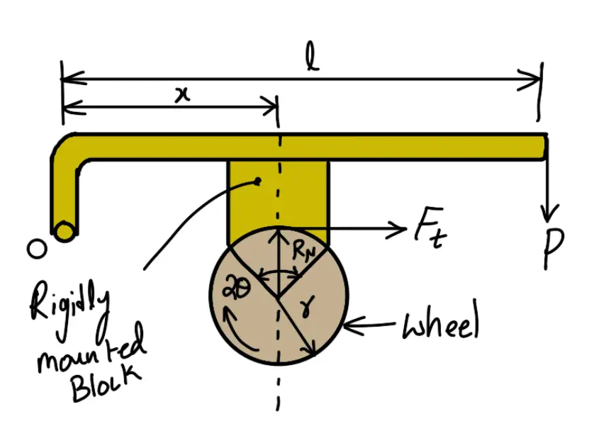
(Line of action of tangential force passes through the fulcrum of the lever.)
Read more about the Single Block or Shoe Brake Here!
Pivoted Block Brake or Pivoted Shoe Brake
We have discussed in the previous article that when the angle of contact is less than 60°, then it may be assumed that the normal pressure between the block and the wheel is uniform. But when the angle of contact is greater than 60°, then the unit pressure normal to the surface of contact is less at the ends than at the center. In such cases, the block or shoe is pivoted to the lever as shown in the following figure, instead of being rigidly attached to the lever.


Read more about the Pivioted Block or Shoe Brake Here!
Double Block Brake or Double Shoe Brake
When a single block brake is applied to a rolling wheel, an additional load is thrown on the shaft bearings due to the normal force (RN). This produces bending of the shaft. To overcome this drawback, a double block or shoe brake as shown in the following figure is used.

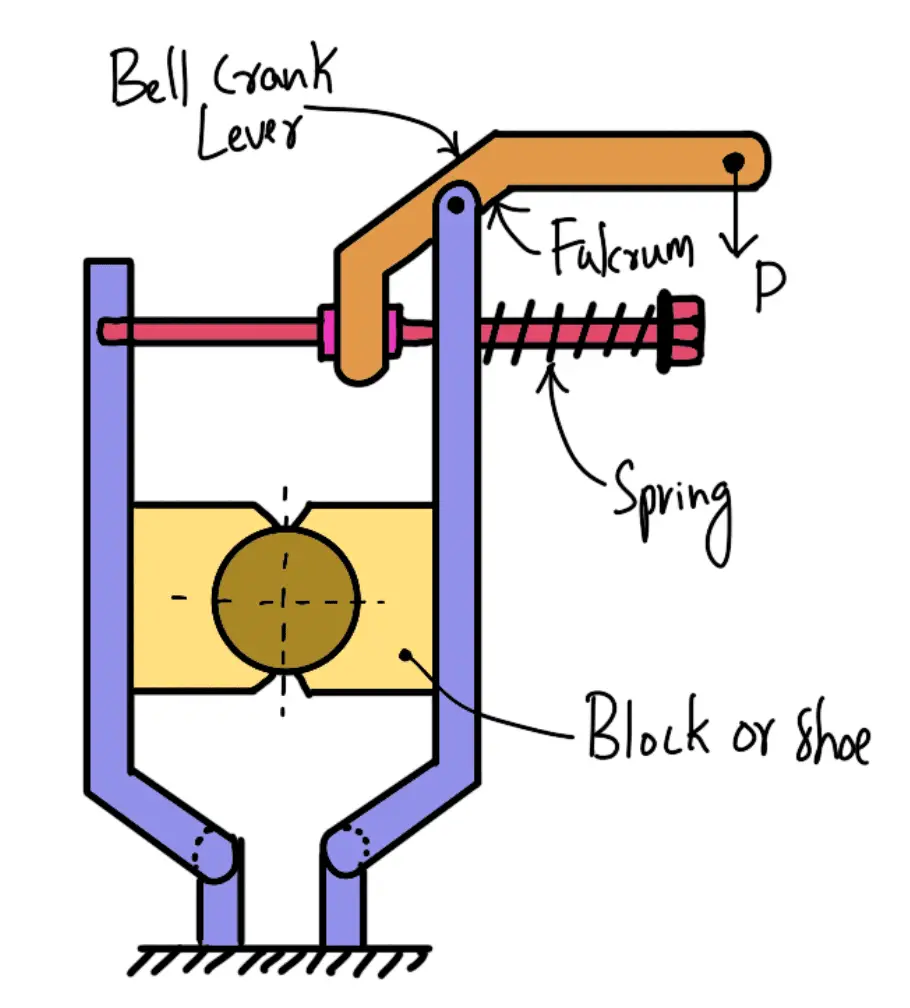
It consists of two brake blocks applied at the opposite ends of a diameter of the wheel which eliminate or reduce the unbalanced force on the shaft.
The brake is set by a spring which pulls the upper ends of the brake arms together. When a force P is applied to the bell crank lever, the spring is compressed and the brake is released.
This type of brake is often used on electric cranes and the force P is produced by an electromagnet or solenoid. When the current is switched off, there is no force on the bell crank lever, and the brake is engaged automatically due to the spring force thus there will be no downward movement of the load.
Read more about the Double Block Brake or Double Shoe Brake Here!
Simple Band Brake
A band brake consists of a flexible band of leather, one or more ropes, or steel lined with friction material, which embraces a part of the circumference of the drum. A band brake, as shown in the following figure, is called a simple band brake in which one end of the band is attached to a fixed pin or fulcrum of the lever while the other end is attached to the lever at a distance b from the fulcrum.
When a force P is applied to the lever at C, the lever turns about the fulcrum pin O and tightens the band on the drum and hence the brakes are applied. The friction between the band and the drum provides the braking force. The force P on the lever at C may be determined as discussed below:

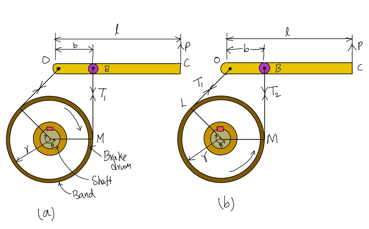
(a) Clockwise Rotation of Drum (b) Anticlockwise Rotation of Drum
Read more about the Simple Band Brake Here!
Differential Band Brake
A band brake consists of a flexible band of leather, one or more ropes, or steel lined with friction material, which embraces a part of the circumference of the drum. A simple band brake in which one end of the band is attached to a fixed pin or fulcrum of the lever while the other end is attached to the lever at a distance b from the fulcrum. In a differential band brake, as shown in the following figure, the ends of the band are joined at A and B to a lever AOC pivoted on a fixed pin or fulcrum O. It may be noted that for the band to tighten, the length OA must be greater than the length OB.

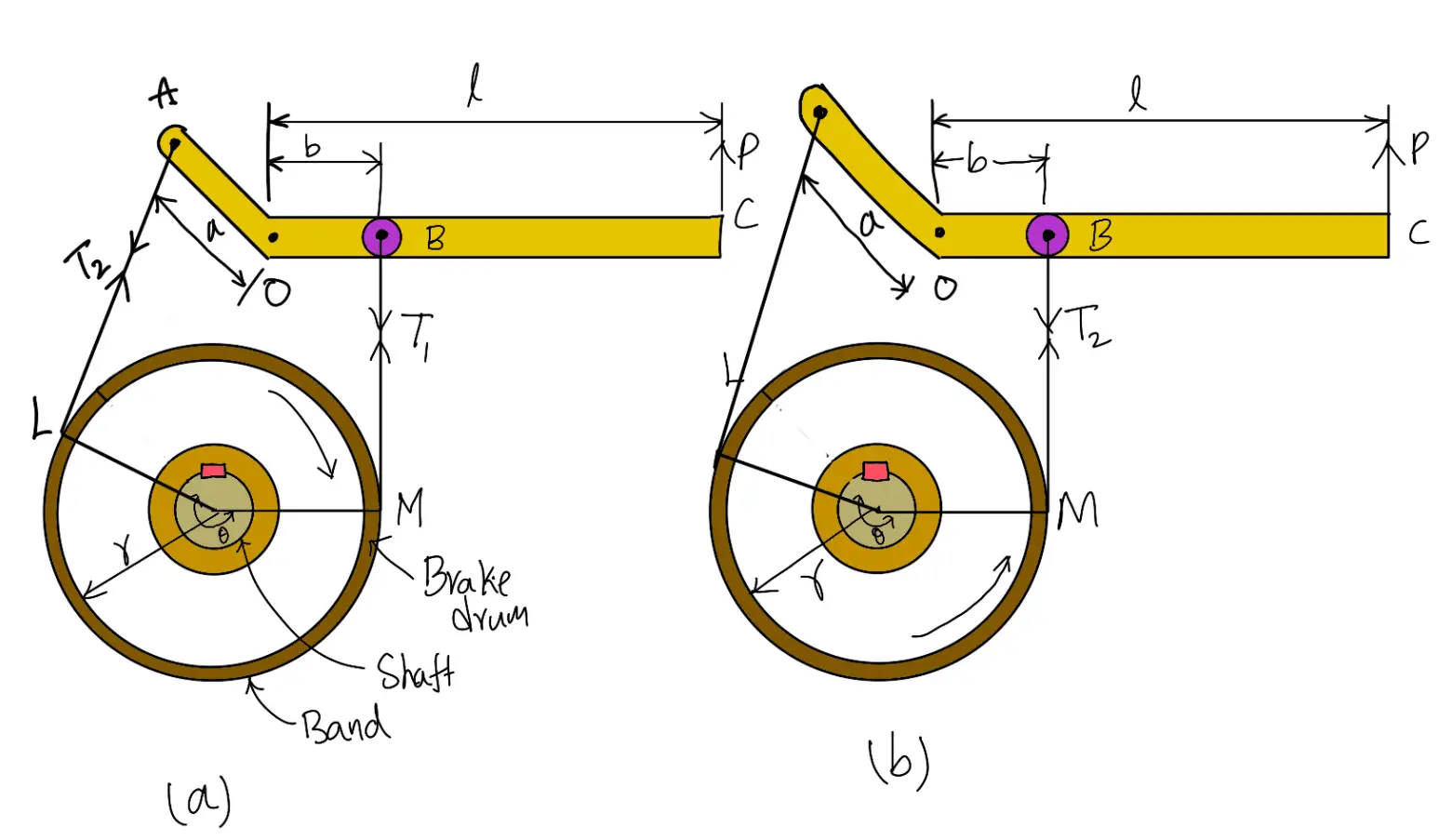
(a) Clockwise Rotation of Drum (b) Anticlockwise Rotation of Drum
Read more about the Differential Band Brake Here!
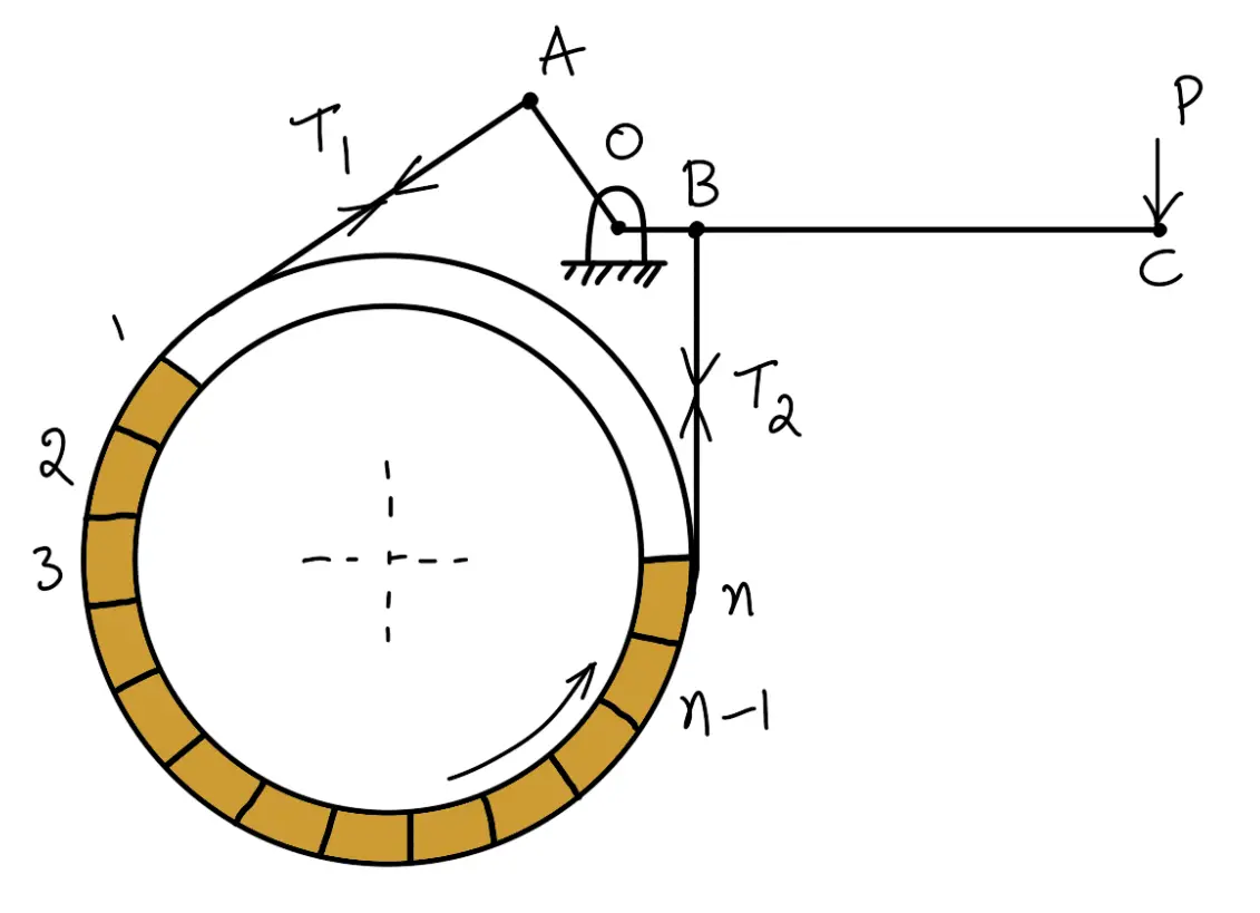
Band and Block Brake
The band brake may be lined with blocks of wood or other material, as shown in the following figure. The friction between the blocks and the drum provides braking action. Let there be an ‘n’ number of blocks, each subtending an angle 2 θ at the center and the drum rotates in an anticlockwise direction.

Read more about the Band and Block Brake Here!
Internal Expanding Brake
An internal expanding brake consists of two shoes S1 and S2 as shown in the following figure. The outer surface of the shoes is lined with some friction material (usually with Ferodo) to increase the coefficient of friction and to prevent the wearing away of the metal. Each shoe is pivoted at one end about a fixed fulcrum O1 and O2 and made to contact a cam at the other end.

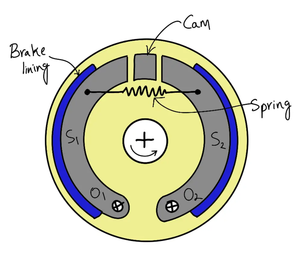
When the cam rotates, the shoes are pushed outwards against the rim of the drum. The friction between the shoes and the drum produces the braking torque and hence reduces the speed of the drum. The shoes are normally held in an off position by a spring as shown in the above figure. The drum encloses the entire mechanism to keep out dust and moisture. This type of brake is commonly used in motor cars and light trucks.
Read more about the Internal Expanding Brake Here!
This is all about the different types of Different Types of Brakes. To read more about these brakes, follow the individual article links to get to know more. Let us know what you think about this article in the comment section below.


