
In recent years, reverse engineering methods have gained significant attention in the automotive industry’s tooling sector. In designing manufacturing automotive parts, tooling profoundly impacts quality, cost, and delivery time. However, traditional craftsmanship still dominates the tool development and manufacturing process, presenting numerous challenges in streamlining and digitizing the process.
Key challenges include ensuring consistency between tool engineering data and actual tools, addressing the lack of 3D digital data reflecting defects and improvements in existing tools, and reducing maintenance hours for copy dies and other tools. Reverse engineering methods are increasingly used to address these challenges in the tool design and manufacturing processes.
Case Study: Using AutoForm-ProcessDesigner®forCATIA Functions with the Panel’s Scanned STL Measurement Data
Outline
Improving work efficiency is crucial in tool springback compensation. This case study, conducted on a backdoor inner part, compared a new compensation method using scanned STL data within AutoForm to the conventional method of manually creating compensated surfaces.
Existing Problems
The conventional manual compensation of surfaces presents several issues:
(1) Substantial man-hours:
When creating compensation surfaces manually, determining the appropriate values is difficult and time-consuming. Values such as compensation amount, rotation angle, and transition areas are often poorly defined or lacking in detail, making successful modifications challenging. For example, achieving the intended shape when deforming a shelf requires determining the optimal location for rotating the shelf around an axis, which is time-consuming. In addition, creating connecting surfaces within the transition area and maintaining the surface quality in these areas further adds to the time required (see Figure 1).

Fig 1: Instructions for compensation surface creation
(2) Imprecise modification instructions:
Manual surface creation often fails to match the expected results in terms of regions and amount of compensation. Detailed instructions regarding the angle and amount of rotation are resource-intensive to create, leading to simplified instructions that result in discrepancies between the intended and actual outcomes.
Methodology of the Case Study
Using the new vector field generation feature in AutoForm, the inverted deviation vector field is calculated from the actual scanned panel. This is used to define the compensation areas and connecting regions at multiple locations, locally compensating the surface. Finally, the resulting surfaces are embedded into a single final shape.
Results Verification
(1) Key advantages:
Several advantages were identified with the new approach using AutoForm:
- Reduced man-hours: The use of vector fields significantly reduced the time spent on manual surface creation, improving work efficiency. AutoForm enabled precise definitions of compensation amounts and springback regions (Figure 2), allowing for closer alignment with real-world phenomena.
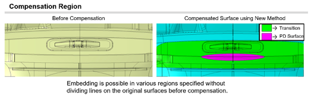
Fig 2: Compensation regions
- Retained surface quality: The surface quality achieved using AutoForm was equivalent to that of conventional manual creation. The method produced geometries that more accurately reflected the springback results, improving the consistency between engineering design and reality. (Figure 3)

Fig 3: Comparison of manual surface creation and surfaces created
(2) Additional considerations:
- Pre-modification of STL data: Some pre-modification of the STL is required before generating vector fields. While AutoForm can filter out some noise, external systems are needed to accurately remove unwanted STL points, such as those in hole areas. (Figure 4)
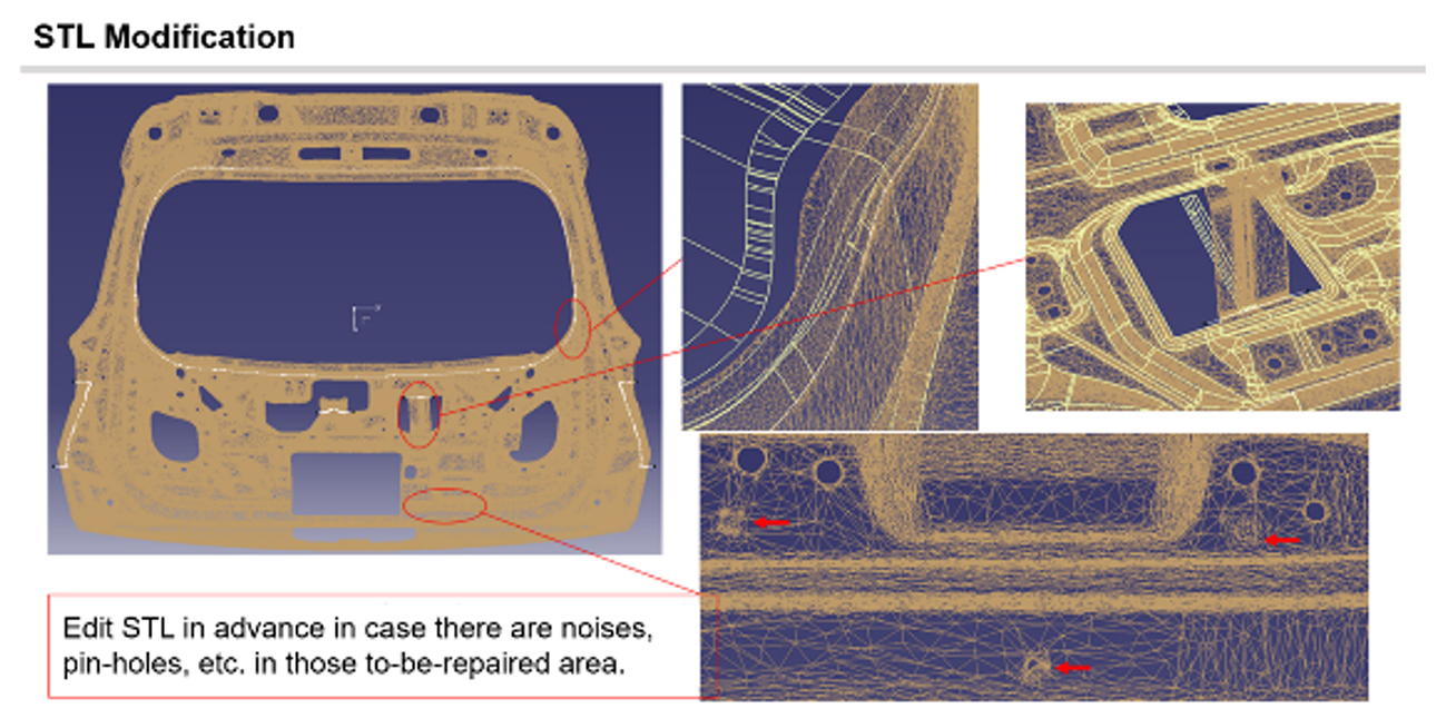
Fig 4: Editing the STL measurement data
- Positioning of STL data: STL data is stored in the reference tool positional orientation, and deviations are calculated as a vector field after applying Best Fit. However, alignment to actual conditions is sometimes necessary. Exploring methods beyond Best Fit can ensure more accurate compensation.
- Area selection for repair: Determining the appropriate method of selecting areas to be repaired, deformed, or connected is essential. If significant compensation is required, the surrounding surfaces may need automatic transition checks, checking each time to ensure the transition region is sufficient to ensure quality results.
(3) Comparison of working hours:
When comparing man-hours, for 15 modification areas, manual surface creation typically takes 35-40 hours. In this case study, pre-editing of STL data took 8 hours. The generation of STL vector fields using the new feature took only a few minutes, and surface creation using the generated vector fields took 8 hours. The entire project took approximately 16 hours, reducing man-hours by more than 50%.
Future Prospects
To deploy this compensation method across future models, we are verifying details and addressing concerns with other parts and processes.
Conclusion
This study showcased the advantages of the new compensation methods for tool surfaces:
(1) Flexibility in compensated surface creation: Using vector fields calculated from scanned STL data allows for localized modifications, even with insufficient instructions for compensation rotation angle or amounts, enabling more flexible surface creation.
(2) Time saving and quality maintenance: Man-hours are reduced to less than half those required for conventional manual surface creation, with equivalent surface quality and accuracy close to reality.
(3) Efficient use of resources: Time previously spent on manual work can now be efficiently allocated, improving productivity.
(4) Integrated work environment: All tasks can be completed within CATIA environment, allowing for compensation and reverse engineering with CATIA surface quality.
Company Overview
Mitsubishi Motors Corporation
Established: April 22, 1970
Location: 3-1-21 Shibaura, Minato-ku, Tokyo
Representative: Takao Kato, Director, Representative Executive Officer, President & CEO
Capital: 284,382,000,000 yen
Net Sales: 2,458,141,000,000 yen (consolidated: as of end of March 2023)
Number of Employees: 28,428 (consolidated: as of end of March 2023)
Business Description: Development, manufacture, and sales of cars and car parts, financial business
URL:https://www.mitsubishi-motors.co.jp/


