Home Blog Page 52

Wooden 3D Puzzles: Designed, Engineered and Manufactured in Ukraine by Ugears

0
Wooden 3D Puzzles: Designed, Engineered and Manufactured in Ukraine by Ugears

What are wooden 3D puzzles?


Wooden 3D puzzles are a type of puzzle that consists of interlocking wooden pieces that can be assembled to form a three-dimensional object or scene. These puzzles can range in complexity, with some having just a few pieces and others having many small pieces that must be precisely fit together. Many wooden 3D puzzles are designed to look like familiar objects or scenes, such as animals, buildings, vehicles, or landscapes. Some popular themes for wooden 3D puzzles include animals, architecture, transportation, and nature.

Wooden 3D puzzles can be a fun and challenging activity for people of all ages. They can help improve spatial reasoning skills, hand-eye coordination, and fine motor skills. They can also be a relaxing and satisfying hobby for those who enjoy the process of solving puzzles and creating something with their hands.

If you are interested in trying wooden 3D puzzles, there are many options available online or at toy and hobby stores. You can choose a puzzle based on your skill level and interests, and there are puzzles available for all age ranges. Some wooden 3D puzzles come with instructions and diagrams to help you assemble them, while others may be more challenging and require you to figure out the solution on your own. Regardless of the type of puzzle you choose, working on a wooden 3D puzzle can be a rewarding and enjoyable activity.

Wooden 3D puzzles have taken the world of engineering-minded DIY enthusiasts by storm, especially with prolifiration of laser cutting techniques in recent years.


Who makes the best wooden 3D puzzles?


Ugears is the world’s leading manufacturer of art-grade composite wooden mechanical 3D puzzles. The models, beloved by fans in 85 countries across 5 continents, are known for their original design and clever engineering. There are models for all ages and abilities, including a line of STEM kits, teaching basic engineering principles in the best way possible: by letting students build common mechanisms like Pendulum or Differential with their own hands.

The company launched in 2014. The first models were powered by rubber bands, but the newer kits are spring-powered, for greater power and durability. This has also allowed Ugears to design sophisticated new models like the Sky Watcher Table Clock, a functional timepiece with a ticking tourbillon mechanism—no small feat for at-home hobbyists!

Wooden 3D Puzzles: Designed, Engineered and Manufactured in Ukraine by Ugears

Developing Ugears wooden 3D puzzles


Development of a new Ugears puzzle takes up to a half a year or more. A designer will prepare a concept, perhaps born of market research, perhaps inspired by hobbies, nature, fantasy, or classic toys. Ugears also creates models under license for major entertainment companies like Warner Bros., releasing several new Harry Potter-themed models just this year.

Ugears wooden 3D puzzles have also been inspired, regrettably, by current events. The company is based between Kyiv and Bucha, where some of the worst atrocities of the war occurred. Ugears’ warehouse was destroyed, with 500 000 dollars’ worth of inventory burnt to ashes. After liberation of the area by Ukraine’s armed forces, Ugears engineers returned to work, responding how they knew best: with a line of models honoring Ukraine’s defenders. The Tractor Wins model depicts a Ukrainian farm tractor towing a damaged Russian tank, while the Bayraktar TB2 is a scaled model of the Turkish drone that has had such outsize success in Ukraine’s defense.

wooden 3d puzzles: ugears tractor ukrainian war

The designer decides on the model’s size, complexity, mechanical elements, and target age range. Basic models are drawn by hand, while more challenging kits get a 3D visualization right from the start. After the idea is agreed by the team and management, the designer develops a detailed 3D model, preparing the files for parts, gears, and mechanisms.

Elaborate mechanisms and non-trivial elements are tested first, to check the design given the limitations of the material. “Our biggest challenge is that any natural material is always different. Each board has a different structure, thickness, and sturdiness within the range. Our job is to guarantee the same quality level even while the characteristics of the material are never the same,” said Robert Milaiev, chief Engineer at Ugears.

Ugears uses several types of 3 or 5-layer art-quality plywood boards of various thicknesses, from 0.8 mm to 3.7 mm. The range for 3-mm and 3.7-mm, boards is usually 2.8-3.1 mm and 3,5-3.8 mm, respectively. The decision on which plywood thickness to use is driven by the model’s size, how powerful the mechanism is, as well as aesthetic considerations. One model may include several different thicknesses of plywood according to the design’s needs. For example, parts of the V-Express train and Drift Cobra racing car are bent during assembly, so these are cut from thinner boards. For extra flexibility, a lined pattern of short cuts is used.

Robert Milaiev, Chief Engineer, Ugears

Each block of parts is tested, and when the designer is satisfied with their work, sample kits are prepared using Ugears’ proprietary manufacturing process and technology. These are then assembled, allowing the team to identify and fix any problems early. The wooden 3D puzzles are then passed along to the engineering team for further development and testing.

wooden 3d puzzle - the laser cutting processRounds of testing and refinement follow, with engineers tweaking the design files. In addition to altering the parts themselves, engineers must refine the composite wood boards, so that the pieces are arranged in a way that reduces breakage and tracks the instructions.

Once the sample kits have been successfully built, production can begin. The composite wood boards are cut to size and manually loaded into laser cutting machines. The laser cuts leave tiny connections, as thin as 0,15-0.2 mm, securing the pieces in the board until a hobbyist presses them out. Ugears checks for product defects—cutting errors, burns, or breakage, with 10-12% of the boards hitting the scrap pile.

The boards are then manually packed into boxes with instruction manuals and any additional materials like metal springs or marbles, sandpaper (for buffing off any small burs), and wax (to lubricate moving gears). No glue or tools are required to build a Ugears puzzle—everything needed for assembly comes right in the box.

The kits are sealed and wrapped using a thermotunnel, packed together and transported to a internal warehouse where they are formed into palettes for overland transport to the Ugears’ distribution facility in Riga, Latvia, for faster international shipping.

After only 8 years Ugears has built an impressive catalog of mechanical wooden 3D puzzles. The company has had many imitators and even outright copycats over the years, but maintains its position as industry leader. This requires the company to devote significant time and resources to new product development, but Ugears believes its well-earned reputation as a committed producer of innovative mechanical models gives it a competitive edge in the marketplace.


Here are the images of the some of the wooden 3D puzzles mentioned in this article.

Wooden 3d Puzzles: Sky Watcher Table Clock by Ugears
Sky Watcher Table Clock by Ugears
wooden 3d puzzles: Hogwards Express by Ugears
Hogwarts Express by Ugears

wooden 3d puzzles by Ugears

Why Integrated STEM Education Rocks!

0
Why Integrated STEM Education Rocks!

Last Updated on July 31, 2024 by Nourhan Essam

STEM education is an approach that focuses mainly on Science, Technology, Engineering, and Mathematics. Traditionally, these subjects are taught separately, e.g., mathematics classes only or science classes only without any integration between the four educational disciplines and also with less focus on technology and engineering applications within the educational curriculum.

In this blog post, we will explore the concept of Integrated STEM education, which aims to provide students with a holistic approach to learning by seamlessly blending the four disciplines of science. We will discuss STEM modules, the impact of creative teaching STEM modules, the conceptual framework for integrated stem education, and more.

The Power of Integrated STEM Education

Why Integrated STEM Education Rocks!Why Integrated STEM Education Rocks!

Integrated STEM education integrates the subject matter of two or more STEM educational disciplines (Science, Technology, Engineering, and Mathematics) to create unique learning experience that aims to create an interest and a lifelong love of science in students from an early age, enabling them to become confident problem solvers in any area of life and supporting the critical analysis skills.

For example, teaching Science using an Engineering process (design-based learning). This approach recognizes that each STEM subject has overlapping, shared skills to offer.

Today, integrated STEM education refers to the combination of engineering and technology concepts into the field of science and mathematics education. Consequently, we can say that the potential of STEM education meets  all requirements to improve the quality of education.

Discover The Role of Digital Platforms in STEM Education .. Read more!

What is Meant By STEM Modules?

The STEM Modules are teacher-made educational units that are developed using the 5E teaching model (i.e., explore, engage, explain, elaborate, evaluate) teaching model.

The STEM modules consist of a combination of academic work, practical works in laboratories, and outdoor activities to enhance the students’ problem-solving skills, critical thinking, innovation, independence, and other critical skills.

The STEM modules stimulate the students in scientific issues, helping them understand the varied roles science plays in our world.

Students will be involved in STEM education topics and will work both in groups and individually;

  • carry out data analysis
  • interpret the results
  • cover robotics and engineering topics
  •  learn about augmented reality
  •  design three-dimensional objects using 3D printers and create their products.

STEM modules consist of a series of activities that aim to understand STEM concepts and detect the best practices for module implementation in the classrooms.

STEM modules can contain teacher -reviewed and approved pretests, surveys, and posttests to measure the students learning’ growth before and after implementation of the STEM module activities and their attitudes towards module- style learning, respectively. 

Examples of STEM Modules:  cultural studies module – environmental education module – historical studies module – civics module – character education module – service leadership module.

Study | The Impact of Creative Teaching STEM Module

The following study aimed to investigate the impacts of enrolling in the creative teaching module in science, technology, engineering, and mathematics (STEM) education from high school students’ perspectives.

 This study applied a case study and qualitative research approach involving 26 Grade 11 students and 31 Grade 8 students.

The creative teaching-STEM (CT-STEM) module, which comprised various activities related to energy literacy in real-world situations for the community’s well-being, involved outdoor STEM education activities with the assistance of two science teachers.

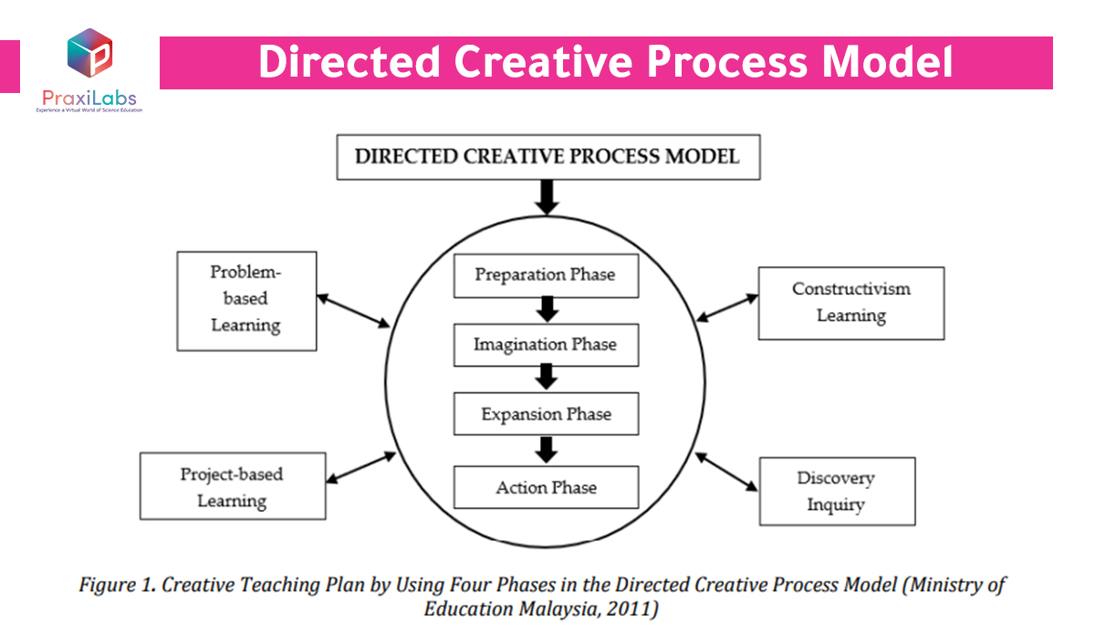
The CT-STEM module was developed based on the directed creative process model by applying four creative teaching strategies:

  •       Constructivist Learning
  •       Discovery inquiry
  •       Problem-based learning
  •       Project-based learning

Figure Shows the Creative Teaching Plan by Using Four Phases in the Directed Creative Process Model Figure Shows the Creative Teaching Plan by Using Four Phases in the Directed Creative Process Model 

The previous figure shows the creative teaching plan by using 4phases in the directed creative process model 

 The results showed that the planned approaches could positively impact and build students’ creativity and create an exciting learning experience. Furthermore, the findings from the open-ended questionnaire instrument, observations, and analysis of the worksheets have shown enhancements in five themes: the development of

  •       Problem-solving skills with an emphasis on the element of sustainability education
  •       High-level thinking skills
  •       Active learning skills
  •       Communication skills
  •       Humanity skills.

The study : EU-jer. Available at: https://pdf.eu-jer.com/EU-JER_11_2_1183.pdf (Accessed: 30 July 2024).

On PraxiLabs, you can find different virtual lab simulations accessible anytime and anywhere. Subscribe and Get Started Now!


A conceptual framework for integrated stem education

Research in integrated STEM can inform STEM education stakeholders to identify barriers as well as determine best practices. A conceptual framework for integrated stem education is helpful to build a research agenda that will, in turn ,inform STEM stakeholders to realize the full potential of integrated STEM education.

Developing a conceptual framework for STEM education requires a deep understanding of the complexities surrounding how people learn, specifically teaching and learning STEM content.

Research shows STEM education is enhanced when the teacher has sufficient content knowledge and domain pedagogical content knowledge.

Instead of teaching content, skills and hoping students will see the connections to real-life application, an integrated approach seeks to locate connections between STEM subjects and provide a relevant context for learning the content. Educators should remain true to the nature in which science, technology, engineering, and mathematics are applied to real-world situations.

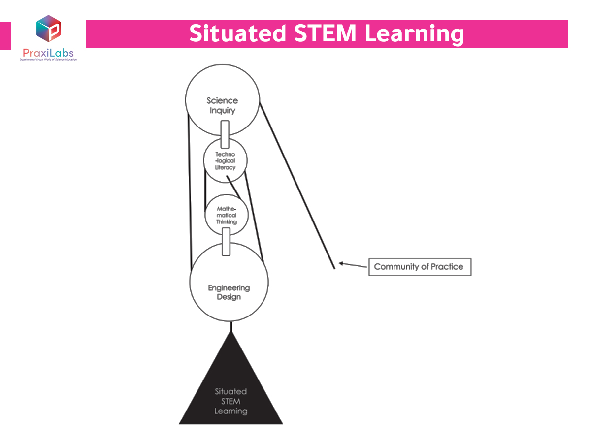
A conceptual framework for integrated stem educationA conceptual framework for integrated stem education

The previous graphic helps capture a conceptual framework for integrated STEM education.

The figure presents a block and tackle of four pulleys to lift  loads  more easily, in this case, “situated STEM learning”. Block and tackle is a pulley system that helps generate mechanical advantage to lift loads easier. The illustration connects

  •  situated learning
  •  engineering design
  •  scientific inquiry
  •  technological literacy
  • and mathematical thinking

 as an integrated system. Each pulley in the system connects common practices within the four STEM disciplines and are bound by the rope of the community of practice. A complex relationship  within  the pulley system must work in harmony to ensure the integrity of the entire system.

It is not suggested that all four domains of integrated STEM must occur during every STEM learning experience, but STEM educators should have a strong understanding of the relationship that can be established across domains and by engaging a community of practice.

Source: (PDF) a Conceptual Framework for integrated STEM education. Available at: https://www.researchgate.net/publication/305418293_A_conceptual_framework_for_integrated_STEM_education (Accessed: 30 July 2024).

Are you tired of seeing your students struggle to grasp complex scientific concepts? Request a Live Demo Now and Increase your Students’ Learning Retention and Engagement With PraxiLabs’ virtual labs!

Integrated STEM Education Unveiled: Your FAQs Clarified

Integrated STEM Education Unveiled: Your FAQs ClarifiedIntegrated STEM Education Unveiled: Your FAQs Clarified

What is integrated stem learning?

Integrated STEM learning is an educational approach that integrates the subject matter of two or more STEM educational disciplines (Science, Technology, Engineering, and Mathematics) to create unique learning experience that aims to create an interest and a lifelong love of science in students from an early age, enabling them to become confident problem solvers in any area of life and support  critical analysis skills.

What is STEM in education?

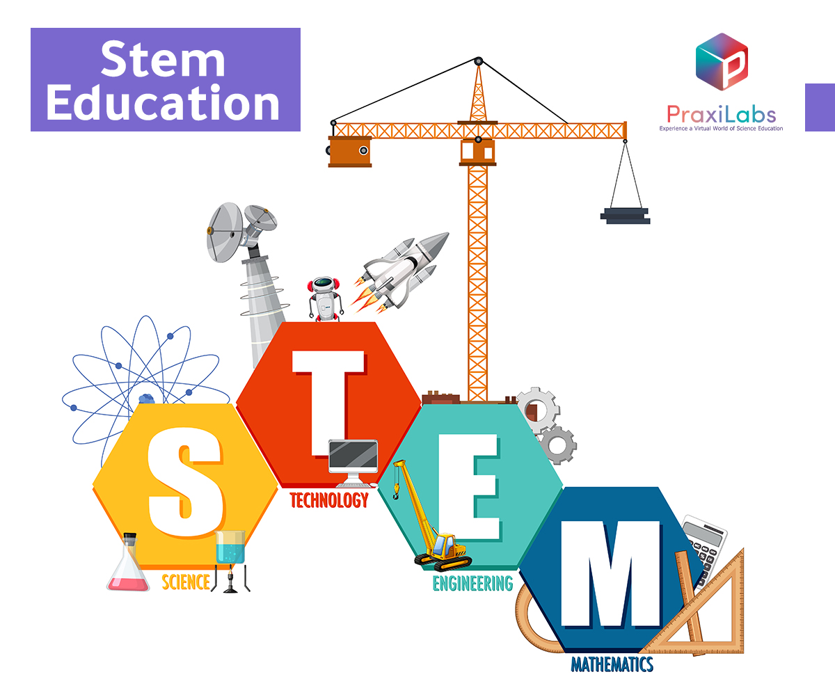
 STEM in education is an abbreviation for the integration of four  educational disciplines:

S ——- Science

T ——- Technology

E ——- Engineering

M —— Mathematics

The integration of these four educational disciplines aims to create an interest in sciences and make students gain and develop critical skills such as critical analysis, creativity, teamwork, communication, initiative, problem-solving, digital literacy, and more.

How to integrate STEM into teaching?

You can integrate STEM into teaching by

  • Understanding the needs and interests of your students.
  • Integrating technology and interactive tools such as virtual labs.
  • Making connections to real-world applications.
  • Celebrating achievements and recognizing your students’ efforts.
  • Fostering collaboration and teamwork.
  • making learning fun and engaging for your students.
  • Providing opportunities for career exploration.
  • Embracing diversity and inclusivity.

What is integrated steam education?

Integrated STEM education is an approach that explores teaching and learning  across any two or more of the STEM subject areas ( Science, Technology, Engineering, and Mathematics), and/or between a STEM subject and one or more other school subjects.

How can we use virtual labs for Integrated STEM education?

Effective learning requires attention. The immersive and interactive 3D virtual STEM labs and simulations go a long way in providing students with the tools that allow for more focus, attention, and engagement. Students remain interested and engaged while staying alert and absorbing the information more easily. The 3D Simulations enhance students’ understanding and knowledge with a virtual hands-on experience of what they’ve learned.

In 2024, virtual labs and simulation spaces will become more prevalent, allowing students to perform their experiments and explore scientific concepts in a virtual environment. This shift is very important as it overcomes the limitations of physical lab spaces, such as safety hazards, high costs, ethical challenges, and high student dropout rates, making hands-on learning more scalable and widely available.

Step into Virtual Labs |Elevate Integrated STEM education with PraxiLabs

Step into Virtual Labs |Elevate Integrated STEM education with PraxiLabsStep into Virtual Labs |Elevate Integrated STEM education with PraxiLabs

Unleash the power of virtual labs with PraxiLabs and revolutionize the way your students experience STEM-based learning. Our 3D interactive virtual lab solution provides students with access to realistic biology, chemistry, and physics labs. 

It enriches their understanding with a variety of informational and educational content to enhance their knowledge and learning, with the aim of providing equal opportunity for enhanced STEM education for students everywhere

Talk to our experts and elevate your integrated STEM education system today!


Battle of the Caucasus: Difference between revisions

0
Battle of the Caucasus: Difference between revisions

Series of Axis and Soviet operations on the Eastern Front of WWII

Battle of the Caucasus
Part of the Eastern Front of World War II
Battle of the Caucasus: Difference between revisions
German tanks in formation in a Caucasus valley with infantry in the foreground, September 1942
Date 25 July 1942 – 12 May 1944 (1942-07-25 – 1944-05-12)
Location
Result Soviet victory
Territorial
changes
Axis withdrawal to Kuban bridgehead in 1943
Axis forces expelled completely in 1944
Belligerents
Nazi Germany Germany
Kingdom of Romania Romania
Slovak Republic (1939–1945) Slovakia


Chechnya-Ingushetia

 Soviet Union
Commanders and leaders
Nazi Germany Wilhelm List
Nazi Germany Ewald von Kleist
Nazi Germany Eberhard von Mackensen
Nazi Germany Richard Ruoff
Kingdom of Romania Petre Dumitrescu


Hasan Israilov 
Mairbek Sheripov 

Soviet Union Semyon Budyonny
Soviet Union Ivan Tyulenev
Soviet Union Ivan Petrov
Soviet Union Ivan Maslennikov
Soviet Union Rodion Malinovsky
Soviet Union Filipp Oktyabrsky
Soviet Union Lev Vladimirsky
Strength
July 1942:
170,000 men
1,130 tanks
4,500 guns and mortars
~1,000 aircraft
January 1943:
764,000 men
700 tanks
5,290 guns and mortars
530 aircraft
July 1942:
112,000 men
121 tanks
2,160 guns and mortars
230 aircraft
January 1943:
1,000,000+ men
~1,300 tanks
11,300+ guns and mortars
900 aircraft
Casualties and losses
281,000 casualties 344,000 casualties

The Battle of the Caucasus was a series of Axis and Soviet operations in the Caucasus as part of the Eastern Front of World War II. On 25 July 1942, German troops captured Rostov-on-Don, opening the Caucasus region of the southern Soviet Union to the Germans and threatening the oil fields beyond at Maikop, Grozny, and ultimately Baku. Two days prior, Adolf Hitler had issued a directive to launch an operation into the Caucasus named Operation Edelweiß. German units would reach their high water mark in the Caucasus in early November 1942, getting as far as the town of Alagir and city of Ordzhonikidze, some 610 km from their starting positions. Axis forces were compelled to withdraw from the area later that winter as Operation Little Saturn threatened to cut them off.

Army Group A – Generalfeldmarschall Wilhelm List

Operation Edelweiß, named after the mountain flower, was a German plan to gain control over the Caucasus and capture the oil fields of Baku on the Eastern Front of World War 2. The operation was authorised by Adolf Hitler on 23 July 1942. The main forces included Army Group A commanded by Wilhelm List, 1st Panzer Army (Ewald von Kleist), 4th Panzer Army (Colonel-General Hermann Hoth), 17th Army (Colonel-General Richard Ruoff), part of the Luftflotte 4 (Generalfeldmarschall Wolfram Freiherr von Richthofen) and the 3rd Romanian Army (General Petre Dumitrescu). Army Group A was supported to the east by Army Group B commanded by Maximilian von Weichs and by the remaining 4th Air Fleet aircraft (1,000 aircraft in all). The land forces, accompanied by 15,000 oil industry workers, included 167,000 troopers, 4,540 guns and 1,130 tanks.

Several oil firms such as “German Oil on the Caucasus”, “Ost-Öl” and “Karpaten-Öl” had been established in Germany. They were awarded an exclusive 99-year lease to exploit the Caucasian oil fields. For this purpose, a large number of pipes—which later proved useful to Soviet oil industry workers—were delivered. A special economic inspection “A”, headed by Lieutenant-General Nidenfuhr was created. Bombing the oil fields was forbidden. To defend them from destruction by Soviet units under the command of Nikolai Baibakov and Semyon Budyonny, an SS guard regiment and a Cossack regiment were formed. The head of the Abwehr developed Operation Schamil, which called for landing in the Grozny, Malgobek and Maikop regions. They would be supported by the local fifth column.

German gebirgsjäger in the Caucasus, Winter 1942

The front from July – November 1942 & December 1942 – February 1943, respectively.

After neutralizing the Soviet counter-attack in the Izyum-Barvenkovsk direction the German Army Group A rapidly attacked towards the Caucasus. When Rostov-on-Don, nicknamed “The Gates of Caucasus,” were reached on 23 July 1942 (falling on the 27th), the tank units of Ewald von Kleist moved towards the Caucasian Mountain Range. The “Edelweiß” division commander, Hubert Lanz, decided to advance through the gorges of rivers of the Kuban River basin and by crossing the Marukhskiy Pass (Maly Zelenchuk River), Teberda, Uchkulan reach the Klukhorskiy Pass, and simultaneously through the Khotyu-tau Pass block the upper reaches of the Baksan River and the Donguz-Orun and Becho passes.

Concurrently with the outflanking maneuvers, the Caucasian Mountain Range was supposed to be crossed through such passes as Sancharo, Klukhorskiy and Marukhskiy to reach Kutaisi, Zugdidi, Sukhumi and the Soviet Georgian capital city of Tbilisi. The units of the 4th German Mountain Division, manned with Tyroleans, were active in this thrust. They succeeded in advancing 30 km toward Sukhumi. To attack from the Kuban region, capture the passes that led to Elbrus, and cover the “Edelweiß” flank, a vanguard detachment of 150 men commanded by Captain (Hauptmann) Heinz Groth, was formed. From the Old Karachay through the Khurzuk aul and the Ullu-kam Gorge the detachment reached the Khotyu-tau Pass, which had not been defended by the Soviet troops. Khotyu-tau gained a new name – “The Pass of General Konrad”.

The starting point of the operation on the Krasnodar-Pyatigorsk-Maikop line was reached on 10 August 1942. On 16 August, the battalion commanded by von Hirschfeld made a feint and reached the Kadar Gorge. On 21 August, troops from the 1st Mountain Division planted the flag of Nazi Germany on the summit of Mount Elbrus, the highest peak in both the Caucasus and Europe.

By 1 November 1942, the German 23rd Panzer Division had reached Alagir and the 13th Panzer Division had reached Ordzhonikidze, approximately 610 km from their starting positions, the high water mark of the Axis invasion of the Caucasus. The 13th Panzer Division was encircled by Red Army counterattacks shortly after however, but was able to break out with assistance from SS Division Wiking. These events led Ewald von Kleist to halt further offensive operations, leading to his replacement weeks later.[1][2]

Some 870,000 Soviet personnel were awarded this Medal “For the Defence of the Caucasus” from 1 May 1944.

There were no military operations in the region in 1941. But the region was affected by warfare elsewhere in the Soviet Union.

In his memoirs, Soviet Transcaucasian Front commander Ivan Tiulenev recounts how thousands of civilians attempted to flee from Ukraine to the comparatively safe Caspian ports, such as Makhachkala and Baku.[citation needed] The Caucasus area became a new area of industry when 226 factories were evacuated there during the industrial evacuations undertaken by the Soviet Union in 1941. After the Grozny to Kiev line was captured during Axis advances, a new link between Moscow and Transcaucasia was established with the construction of the new railway line running from Baku to Orsk (via Astrakhan), bypassing the front line at Grozny, while a shipping line was maintained over the Caspian Sea through the town of Krasnovodsk in Turkmenistan.

In 1942, the German Army launched Operation Edelweiß which was aimed at advancing to the oil fields of Azerbaijan. The German offensive slowed as it entered the mountains in the southern Caucasus and did not reach all of its 1942 objectives. After the Soviet breakthroughs in the region around Stalingrad, the German forces in the Caucasus were put on the defensive.

Soviet military operations included

Tikhoretsk-Stavropol Defensive Operation (25 July – 5 August 1942)
Armavir-Maikop Defensive Operation (6–17 August 1942)
Novorossiysk Defensive Operation (19 August – 26 September 1942)
Mozdok-Malgobek Defensive Operation (1–28 September 1942)
Tuapse Defensive Operation (25 September – 20 December 1942)
Nalchik-Ordzhonikidze Defensive Operation (25 October – 12 November 1942)
Red Army units enter the reconquered city of Mozdok (January 1943).
Residents of Kislovodsk unearthing the corpses of their relatives, shot by German troops, January 1943

In early 1943, the Germans began to withdraw and consolidate their positions in the region due to setbacks elsewhere. They established a defensive line (Kuban bridgehead) in the Taman Peninsula from which they hoped to eventually launch new operations in the Caucasus. The fighting remained reasonably static until September 1943 when the Germans ordered fresh withdrawals which effectively ended the period of fighting in the Caucasus.

Soviet Operations in 1943 consisted of the following.

North Caucasus Strategic Offensive (Operation Don)

Salsk-Rostov Offensive (1 January – 4 February 1943)
Mozdok-Stavropol Offensive (1 January – 24 January 1943)
Novorossiysk-Maikop Offensive (11 January – 4 February 1943)
Tikhoretsk-Eisk Offensive (24 January – 4 February 1943)
Rostov Offensive (5–18 February 1943)
Krasnodar Offensive (9 February – 24 May 1943)
Novorossiysk-Taman Operation (10 September – 9 October 1943)

The key military base of Novorossiysk was retaken in September, 1943.

  • 3 January 1943 – Red Army retakes Mozdok
  • 21 January 1943 – Red Army retakes Stavropol
  • 23 January 1943 – Red Army retakes Armavir
  • 29 January 1943 – Red Army retakes Maykop
  • 4 February 1943 – Soviet marines repel a German attempt to land at Malaya Zemlya, an island fort that controlled access to the port at Novorossiysk. Soviets hold this island until relieved in September, denying the use of the port to the Germans.
  • 12 February 1943 – Red Army retakes Krasnodar
  • 16 February 1943 – Red Army retakes Rostov
  • 9 September 1943 – the Germans begin to retreat from the Blue Line defensive positions
  • 16 September 1943 – Red Army occupies Novorossiysk, relieving the sailors and marines at Malaya Zemlya.
  • 9 October 1943 – Red Army controls the whole of the Taman Peninsula

During the Winter Spring Campaign of 1944 (1 January – 31 May), the Soviet army was able to launch an invasion of the Crimea from the Caucasus, which was fully recaptured by 12 May 1944.

Operations included:

Kerch-Eltigen Amphibious Offensive Operation (31 October 1943 – 11 December 1944)
Perekop–Sevastopol Offensive (8 April – 12 May 1944)
Kerch–Sevastopol Offensive (11 April – 12 May 1944)

Anti-Soviet insurgency (1940–1944)

[edit]

  • Alexander Werth, The Battle of Stalingrad, Chapter 7, “Caucasus, there and back”, pp. 648–651
  • Ivan Tyulenev, “Cherez Tri Voyny” (Through Three Wars), Moscow, 1960, p. 176.
  • (in Russian) Иван Тюленев. Крах операции “Эдельвейс”. Орджоникидзе, 1975.
  • (in Russian) К.-М. Алиев. В зоне “Эдельвейса”. М.-Ставрополь, 2005.
  • Javrishvili K. Battle of Caucasus: Case for Georgian Alpinists, Translated by Michael P. Willis, 2017.

Artificial Brain Takes Top Prize in ‘Emerge Track’ at U.S. Defense Accelerator Hustle, Secures $100K in Funding

0
Artificial Brain Takes Top Prize in ‘Emerge Track’ at U.S. Defense Accelerator Hustle, Secures 0K in Funding

Insider Brief

  • Artificial Brain USA won first prize in the “Emerge Track” at the U.S. Defense Accelerator, Hustle, securing $100K to scale its quantum technology solutions.
  • The team spent three months at Griffiss Institute and Innovare Advancement Center, collaborating with the Air Force Research Lab and U.S. defense partners.
  • CEO Jitesh Lalwani and Senior Executive Dana Linnet highlighted the importance of mentorship, partnerships, and future growth in Rome, NY, as the company continues its work in defense and energy sectors.

PRESS RELEASE — Artificial Brain USA, a leader in quantum software technology, is proud to announce that it won first prize in the “Emerge Track” at the U.S. Defense Accelerator, Hustle. Co-sponsored by AFRL, National Grid, and the State of New York, the prize includes $100K in funding for Artificial Brain to scale company operations to deliver cutting-edge quantum technology solutions.

During a nearly 3-month stay at the Griffiss Institute and Innovare Advancement Center in Rome, NY, the Artificial Brain team had the opportunity to work closely with experienced mentors and create relationships with the U.S. R&D and Defense establishments including the Air Force Research Lab (AFRL) and other key partners.

“We are thrilled to receive this recognition and funding,” said Jitesh Lalwani, Founder & CEO. “The guidance from our mentors and industry experts has been invaluable. It was also inspiring to collaborate with other innovative tech startups working in Space, GenAI, Cybersecurity, and Autonomous aircraft.”

With China investing heavily in quantum technology, the U.S. has an opportunity to lead the charge in applied Quantum software development. Accelerator programs like Hustle play a crucial role in supporting American innovators like Artificial Brain in this global competition.

Artificial Brain Takes Top Prize in ‘Emerge Track’ at U.S. Defense Accelerator Hustle, Secures 0K in Funding

We wish to extend special thanks to Heather Hage and Seth Mulligan for their steadfast support. “This is just the beginning.  We are now hiring in Rome, NY, at Griffiss, where we can meet the opportunities and build out our relationships with Hustle and our defense and energy customers for many years to come,” added Dana Linnet, Artificial Brain’s Senior Executive.

Definition, Types, Resonance, and Formula

0
Definition, Types, Resonance, and Formula

An LC circuit, also known as a resonant or tank circuit, is an electrical circuit that consists of two key components: an inductor (L) and a capacitor (C). The inductor is a coil of wire that stores energy in the form of a magnetic field when current flows through it. On the other hand, the capacitor is a device that stores energy in the form of an electric field when a voltage is applied across its plates. When these two components are connected, they form a system capable of oscillating electrical energy back and forth between the magnetic field of the inductor and the electric field of the capacitor.

Definition, Types, Resonance, and Formula

Types of LC Circuit

Series LC Circuit

In a series LC circuit, the inductor and capacitor are connected one after the other in a single loop or path. It means that the same current flows through both components and continues in this loop.

Series LC Circuit

Parallel LC Circuit

In a parallel LC circuit, the inductor and capacitor are connected side by side, forming two separate branches. It means that the current flowing through the inductor is different from the current flowing through the capacitor. The total current in the circuit is split between these two components, depending on their characteristics.

Parallel LC Circuit

Resonance in LC Circuit

In an LC circuit, resonance is a special condition that occurs when the energy stored in the inductor and the capacitor is perfectly balanced, causing the circuit to oscillate at a particular frequency.

The capacitor stores energy in an electric field when it is charged, while the inductor stores energy in a magnetic field when current flows through it. During resonance, these two components continuously exchange energy. When the capacitor is fully charged, it begins to discharge, sending current through the inductor. This current generates a magnetic field in the inductor, which then collapses and returns the energy to the capacitor, repeating the cycle.

This back-and-forth transfer of energy creates oscillations, much like a pendulum swinging back and forth. The frequency at which this energy transfer happens is called the resonant frequency and is given by the formula:

\[ f_0 = \frac{1}{2\pi \sqrt{LC}} \]

Where L is the inductance of the inductor, and C is the capacitance of the capacitor. The resonant frequency depends on both these values; smaller inductors or capacitors lead to a higher resonant frequency, while larger values lead to a lower one.

At resonance, something important happens: the impedance, which is the total opposition to current flow in the circuit, is at its lowest point in a series LC circuit. It means that the circuit allows the maximum amount of current to flow. This property of resonance is what makes LC circuits useful in many applications.

Applications

Tuning Circuits: LC circuits are essential in radios, televisions, and other communication devices for selecting a specific frequency from a wide range of signals. By adjusting the values of the inductor and capacitor, the circuit resonates at a desired frequency, allowing it to pick up only that signal.

Filters: LC circuits are used to filter signals in electrical devices. They can act as:

Low-pass filters: Allow low-frequency signals to pass while blocking higher frequencies.

High-pass filters: Allow high-frequency signals to pass while blocking lower frequencies.

Band-pass filters: Allow a specific range of frequencies to pass, making them useful in audio and communication systems.

Oscillators: LC circuits can generate stable, specific frequencies when connected to amplifying devices. These oscillators are used in electronic equipment like signal generators, clocks, and radio transmitters.

Article was last reviewed on Monday, October 14, 2024

Nobel winners who have graced our silver screen – Physics World

0
Nobel winners who have graced our silver screen – Physics World


Laureates on film: Nobel winners who have graced our silver screen – Physics World


Skip to main content


Nobel winners who have graced our silver screen – Physics World

Discover more from Physics World


Copyright © 2024 by IOP Publishing Ltd and individual contributors

Types Of Hammers and their Uses

0
Types Of Hammers and their Uses

Hammers are some of the most essential tools in any toolbox. They come in different types and sizes, each designed for specific purposes. If you’re doing any kind of construction work, DIY projects, or repairs around the house, you need to have the right hammer for the job. In this article, I will explore the different types of hammers available, their uses, and how to choose the right one for your needs.

Introduction to Hammers

Hammers have been around for centuries and have evolved over time to become more efficient and effective. They are hand-held tools that use a heavy head to deliver a powerful blow to an object. The head is usually made of metal, and the handle is made of wood, plastic, or fiberglass.

The primary purpose of a hammer is to drive nails into wood or other materials, but they can also be used for demolition, shaping, bending, and breaking objects. Hammers are versatile tools that are used in various industries, including construction, manufacturing, and automotive repair.

The Importance of Using the Right Hammer

Using the right hammer for the job is crucial for efficiency, safety, and achieving the desired results. Using the wrong hammer can damage the object you’re working on, cause injury, or make the job more difficult than it needs to be.

For example, using a claw hammer to drive a chisel through concrete will not work effectively. The claw hammer is designed for pulling nails and driving them into wood, not for breaking concrete. Using a sledgehammer for small jobs like hanging a picture frame can cause damage to the wall and make the job more difficult than it needs to be.

Common Types of Hammers

There are many different types of hammers available, each designed for specific purposes. In this section, we’ll explore the most common types of hammers and their uses.

Types Of Hammers and their Uses
types of hammers

Claw Hammers and Their Uses

The claw hammer is the most common type of hammer and is used for driving nails into wood or other materials. It has a flat face for driving nails and a curved claw for pulling them out. The claw hammer comes in different sizes, weights, and handle materials.

The most common sizes are 16 oz and 20 oz, and the most common handle materials are wood, fiberglass, and steel. The claw hammer is ideal for DIY projects, construction, and woodworking.

Ball Peen Hammers and Their Uses

The ball peen hammer is also known as the machinist hammer and is used for shaping and bending metal. It has a flat face on one end and a rounded ball on the other end. The ball is used for shaping metal, while the flat face is used for striking punches and chisels.

The ball peen hammer comes in different sizes, weights, and handle materials. The most common sizes are 16 oz and 32 oz, and the most common handle materials are wood, fiberglass, and steel. The ball peen hammer is ideal for metalworking, blacksmithing, and automotive repair.

Sledge Hammers and Their Uses

The sledgehammer is a heavy-duty hammer that is used for demolition, breaking concrete, and driving stakes into the ground. It has a long handle and a large, heavy head that delivers a powerful blow. The sledgehammer comes in different sizes and weights, ranging from 2 lbs to over 20 lbs.

The most common handle materials are wood and fiberglass, and the head is made of steel. The sledgehammer is ideal for demolition, construction, and landscaping.

Dead Blow Hammers and Their Uses

The dead blow hammer is a specialized hammer that is used for striking objects without causing damage. It has a hollow head that is filled with sand or steel shot, which absorbs the shock of the blow and prevents rebound. The dead blow hammer comes in different sizes and weights, ranging from 8 oz to 5 lbs.

The most common handle materials are rubber and plastic, and the head is made of polyurethane. The dead blow hammer is ideal for automotive repair, woodworking, and metalworking.

Rubber Mallets and Their Uses

The rubber mallet is a non-damaging hammer that is used for striking objects that may be damaged by a metal hammer. It has a rubber head that absorbs shock and prevents damage to the object being struck. The rubber mallet comes in different sizes and weights, ranging from 8 oz to 5 lbs.

The most common handle materials are wood, plastic, and fiberglass, and the head is made of rubber. The rubber mallet is ideal for woodworking, upholstery, and automotive repair.

Blacksmith Hammers and Their Uses

The blacksmith hammer is a specialized hammer that is used for forging metal. It has a long handle and a heavy head that delivers a powerful blow. The blacksmith hammer comes in different sizes and weights, ranging from 2 lbs to over 10 lbs.

The most common handle materials are wood and fiberglass, and the head is made of steel. The blacksmith hammer is ideal for blacksmithing and metalworking.

War Hammers and Their Uses

The war hammer is a historical hammer that was used in combat. It has a long handle and a heavy head that was used for striking armor and weapons. The war hammer comes in different sizes and weights, ranging from 2 lbs to over 10 lbs.

The most common handle materials are wood and steel, and the head is made of steel. The war hammer is ideal for historical reenactments and collectors.

Reflex Hammers and Their Uses

The reflex hammer is a medical hammer that is used for testing reflexes. It has a small, rubber head that is used to strike the knee or other parts of the body to elicit a reflex response. The reflex hammer comes in different sizes and weights, ranging from 2 oz to 8 oz.

The most common handle materials are plastic and metal, and the head is made of rubber. The reflex hammer is ideal for medical professionals and students.

Antique Hammers and Their Uses

Antique hammers are collectible hammers that have historical significance. They come in different shapes, sizes, and materials, and are highly sought after by collectors. Antique hammers can be used for their original purpose or kept as a decorative item.

Electric Hammers and Their Uses

Electric hammers are power tools that use a motor to deliver a powerful blow. They come in different types, including rotary hammers, demolition hammers, and hammer drills. Electric hammers are ideal for heavy-duty jobs that require a lot of power.

Choosing the Right Hammer for Your Needs

Choosing the right hammer for your needs depends on the job you’re doing and your personal preferences. Here are some factors to consider when choosing a hammer:

  • Type of job: Consider the type of job you’re doing and choose a hammer that is designed for that purpose.
  • Size and weight: Choose a hammer that is comfortable to hold and use for an extended period.
  • Handle material: Choose a handle material that is comfortable to grip and absorbs shock.
  • Head material: Choose a head material that is durable and appropriate for the job.

Conclusion: The Versatility of Hammers

Hammers are versatile tools that are used in various industries and for different purposes. Choosing the right hammer for the job is crucial for efficiency, safety, and achieving the desired results. With the right hammer, you can complete your projects with ease and precision.

If you’re looking to buy a hammer, consider the different types available and choose one that is suitable for your needs. Whether you’re a DIY enthusiast or a professional tradesperson, having the right hammer in your toolbox can make all the difference.

Sachin Thorat

Sachin is a B-TECH graduate in Mechanical Engineering from a reputed Engineering college. Currently, he is working in the sheet metal industry as a designer. Additionally, he has interested in Product Design, Animation, and Project design. He also likes to write articles related to the mechanical engineering field and tries to motivate other mechanical engineering students by his innovative project ideas, design, models and videos.

Recent Posts

link to Top Branches of Mechanical Engineering

Top Branches of Mechanical Engineering

Mechanical Engineering is an essential discipline of engineering encompassing many specializations, with each contributing its unique aspect to the dynamic and inventive nature of this field. With…

link to Shree Ram Ayodhya Murti, idol – Vector , Wallart

Shree Ram Ayodhya Murti, idol – Vector , Wallart

The Ram Lalla idol, which is installed at Ayodhya’s Ram temple has many significant religious symbols from Hinduism. All 10 incarnations of Lord Vishnu are engraved on the idol. Notably, Lord Ram is…

SCHUMER, GILLIBRAND, MORELLE ANNOUNCE OVER $5 MILLION FROM THE DEPARTMENT OF DEFENSE TO BOLSTER MONROE COMMUNITY COLLEGE AS ONE OF THE ONLY COMMUNITY COLLEGE OPTICS & PHOTONICS TRAINING CENTERS IN THE NATION AND GIVE FINGER LAKES WORKERS THE SKILLS THEY NEED FOR GOOD PAYING TECH CAREERS VITAL TO NATIONAL SECURITY

0
SCHUMER, GILLIBRAND, MORELLE ANNOUNCE OVER  MILLION FROM THE DEPARTMENT OF DEFENSE TO BOLSTER MONROE COMMUNITY COLLEGE AS ONE OF THE ONLY COMMUNITY COLLEGE OPTICS & PHOTONICS TRAINING CENTERS IN THE NATION AND GIVE FINGER LAKES WORKERS THE SKILLS THEY NEED FOR GOOD PAYING TECH CAREERS VITAL TO NATIONAL SECURITY

SCHUMER, GILLIBRAND, MORELLE ANNOUNCE OVER  MILLION FROM THE DEPARTMENT OF DEFENSE TO BOLSTER MONROE COMMUNITY COLLEGE AS ONE OF THE ONLY COMMUNITY COLLEGE OPTICS & PHOTONICS TRAINING CENTERS IN THE NATION AND GIVE FINGER LAKES WORKERS THE SKILLS THEY NEED FOR GOOD PAYING TECH CAREERS VITAL TO NATIONAL SECURITY

Monroe Community College Is One Of The Only Community Colleges In The Nation Offering An Optics and Photonics Associates Degree, Needed Federal Funds To Strengthen Facilities, Meet Regional Need For Trained Photonics Workers

Schumer Fought To Secure Critical Fed Boosts in the FY 23 Omnibus Appropriations Bill To Allow MCC To Strengthen Its World Class Optics & Photonics Degree Programs – Helping To Give Workers The Skills They Need For Major Local Employers And Build Up Workforce Vital To America’s Nation Security


Schumer, Gillibrand, Morelle: MCC And The Rochester-Finger Lakes Region Are Catching Eye Of DoD With Major Fed Investment In Optics & Photonics Training

U.S. Senate Majority Leader Charles E. Schumer, U.S. Senator Kirsten Gillibrand, and U.S. Congressman Joe Morelle today announced a $5.1 million 3-year grant award for Monroe Community College’s (MCC) optics program from the U.S. Department of Defense’s (DoD) Manufacturing Engineering Education Program (MEEP). Schumer, Gillibrand, and Morelle secured a critical increase for this program allowing MCC to tap this funding to help grow their program as previous funding was set to expire this month.  The representatives explained this major multi-year grant will provide the critical resources to fund MCC’s optics and photonics associate degree programs, providing Rochester optics and photonics companies the skilled workforce to fill good paying jobs in the region that are vital to our national security.

“Rochester has long been known for eye catching industries, and now after years of advocating for the growth of the vital optics and photonics industry, I was proud to secure the funding needed for the Department of Defense to double down on Monroe Community College as a major focus for training the optics workforce vital to our national security.  The Rochester optics industry, which boasts well over 100 optics companies that employ 18,000 workers, relies on MCC to train the next generation of skilled optical workers it needs to grow.  MCC is a proven leader in optics and photonics training with one of the first and only associate degrees in optics training and today we are building on that success by connecting local Rochester and Upstate New York students to good-paying Rochester jobs in this cutting edge field,” said Senator Schumer. “I am proud to deliver this major $5+ million federal grant, made possible by the critical increase I was able to secure in the FY23 Omnibus Bill, so that Monroe Community College can continue to train the next generation of optics technicians that are crafting the vision of our technological future.”

“For years, Monroe Community College has been training workers for careers in optics and photonics, jobs that are vital to our national security,” said Senator Gillibrand. “This funding will provide MCC with the crucial resources needed to prepare Finger Lakes workers for good-paying jobs and boost the local economy. I am proud to announce this funding and will continue to fight to provide resources to train workers for jobs that support our national defense.

“Congratulations to Monroe Community College on receiving this prestigious and well-deserved Manufacturing Engineering Education Program award,” said Congressman Morelle. “This investment in our burgeoning optics workforce is not only key to our national defense, but also a conduit to enhancing our local economy and cementing our place as a regional tech hub. I’m grateful to Senator Schumer and Senator Gillibrand for sharing this vision and appreciate their support for this funding.”

DeAnna R. Burt-Nanna, Ph.D., President of Monroe Community College said, “Monroe Community College continues building on its efforts to strengthen the talent pipeline across the Finger Lakes region to ensure a robust optics technician workforce. In 2023, MCC graduated the most students in the optical systems technology program’s history and has seen increased student enrollment in the program over the past two years. This latest federal funding support will enable MCC to create opportunities for more residents, especially those in historically underrepresented communities, to secure a family-sustaining career in the high-demand advanced manufacturing industry. We are grateful to Senators Schumer and Gillibrand and Representative Morelle for their leadership and support of our shared vision to advance the economic mobility of residents across all ZIP codes and bolstering our regional economy.”

Tom Battley, Executive Director, New York Photonics said, “The longest-standing precision optics program in the United States, at Monroe Community College in Rochester, NY, led by Professor Alexis Vogt, is recognized around the country and around the world as the leading program of its kind. And the graduates have 100% job placement. Colleges around the country and precision optics manufacturers around the country are eager to learn how MCC does it.  Precision optics are essential in everything from defense and biotech applications to satellites and quantum technologies.  We count ourselves extremely lucky that our Washington delegation understands the importance of this critical program.

Schumer, Gillibrand, and Morelle explained the DoD’s MEEP invests in programs that better position the current and next-generation manufacturing workforce vital for our nation’s military systems and components that assure defense technological superiority. This is second time MCC has been awarded funding through the MEEP program, as the nation’s first community college to administer associate degrees in precision optics.  With this latest round of funding MCC will be able to strengthen its existing program to grow the national workforce for the optics industry and give workers the skills they need for careers with major local employers in the region in the optics and photonics industry. Specifically, MCC seek to grow enrollement for this program for the highly in demand optics industry and seek to establish new training and apprenticeship opportunities.

Schumer, Gillibrand, and Morelle have been longtime advocates for Monroe Community College’s optics and photonics degree programs. In 2017, following their relentless advocacy, the representatives secured over $550,000 from the National Science Foundation’s (NSF) Advanced Technology Foundation’s Education program for MCC to expand its optics and photonics degree programs, purchase new equipment, as well as develop a new curriculum and expand student outreach. Today’s award is a direct result of Senators Schumer, Gillibrand and Rep Morelle’s work to secure $15 million in federal funding in FY23 for the DoD’s Manufacturing Engineering Education Program (MEEP), allowing MCC to apply for the funding they received today, and the senator personally advocated to Defense Secretary Austin on MCC’s behalf to strengthen their program.

A copy of Schumer’s original letter to the DoD appears below

Dear Secretary Austin:

I am pleased to write in support of the application submitted by Monroe Community College (MCC) to the Department of Defense’s Manufacturing Engineering Education Program. MCC’s “Defense Engineering Education Program – Enhancing Results in Optics” (DEEPER OPS) program will build on MCC’s past awards to bolster the national precision optics workforce and continue Rochester, NY’s legacy as the global leader in optics education, manufacturing, and research.

With the CHIPS and Science Act, Congress has made it a priority to bolster our technically-skilled workforce across the nation. This is crucial as post-pandemic issues continue to affect our supply chains, and cause labor shortages and gaps in skilled talent. Monroe County specifically has a major role in the photonics, imaging, and optics environment with over 150 STEM research and advanced manufacturing companies, and their need for skilled workers will only continue to grow. MCC plays a critical role in supplying talent for this network; however, they currently do not have enough graduates to meet the demand for skilled technicians.

With funding, MCC would grow our national workforce and ensure continued technological superiority for the Department of Defense by enhancing precision optics technician training, grow enrollment and graduation of participants, particularly females, single parents, low-income and underrepresented groups, as well as veterans, and lastly establish direct engagement and outreach between students and the optics industry.

MCC’s DEEPER OPS proposal will build on the framework of their first MEEP grant and will reach more than 3,000 precollegiate students, apprentices, and incumbent workers. It will also establish 50 apprenticeships and engage 15 industry sponsors, illustrating the strong program and support MCC has across the community.

I applaud Monroe Community College for their foresight and I sincerely hope the application meets with your approval.

Thank you for your consideration. Please do not hesitate to contact me or my Grants Coordinator in my Washington, DC office at 202-224-6542.

Sincerely,

Inconsistent conventions in vector notations

0
Inconsistent conventions in vector notations

Dealing with vectors, we usually follow the two following conventions:

CONVENTION $\boldsymbol 1$:

Vectors are denoted with an arrow; their magnitude is denoted by the same letter without the arrow.

For example, $\vec v$ is a vector and $v$ is its magnitude.

CONVENTION $\boldsymbol 2$:

The vector components of the bidimensional vector $\vec v$ are denoted by $\vec v_x$ and $\vec v_y$. The scalar components of the bidimensional vector $\vec v$ are denoted by $v_x$ and $v_y$.

The vector components are the only two vectors, one parallel to the $x$ axis and one parallel to the $y$ axis, such that $\vec v = \vec v_x + \vec v_y$:

Inconsistent conventions in vector notations

The scalar components are the only two numbers such that $\vec v = v_x \hat x + v_y \hat y$, where $\hat x$ and $\hat y$ are the unit vectors in the direction of the $x$ axis and the $y$ axis, respectively.

These two conventions are inconsistent because, based on convention $1$, one would expect $v_x$ to be the magnitude of $\vec v_x$, which implies that $v_x \geq 0$. However, based on convention $2$, $v_x <0$ for the vector represented in the drawing.

There isn’t any major conceptual difficulty here, but I keep noticing that the high school students I tutor find this extremely confusing. Do any of you know of some nice notation for vector components and scalar components that avoids this issue?

Ameh (Nigerian name): Difference between revisions

0
Ameh (Nigerian name): Difference between revisions

From Wikipedia, the free encyclopedia

Content deleted Content added


Line 7: Line 7:

* [[Ada Ameh]] ( 1974 -2022) Nigerian actress

* [[Ada Ameh]] ( 1974 -2022) Nigerian actress

* [[Ameh Ebute]] (born 1946) Nigerian politician and lawyer

* [[Ameh Ebute]] (born 1946) Nigerian politician and lawyer

* [[Aruwa Ameh]] (1990- 2011) Nigerian footballer

== References ==

== References ==


Latest revision as of 13:03, 17 October 2024

Ameh
Gender Male
Language(s) Igala
Word/name Igala & Idoma
Meaning “There is an end to everything”
Region of origin Middle belt, Nigeria

Ameh is a masculine given name and surname of Benue origin, and it means “There is an end to everything.” [1][2]The name is commonly found among the Igala and Idoma people in the Middle Belt region of Nigeria. [3][4]

Notable people with the name & surname

[edit]

Ameh (Nigerian name): Difference between revisions