Home Blog Page 61

New York Photonics 2023 Annual Meeting

0
New York Photonics 2023 Annual Meeting

New York Photonics 2023 Annual Meeting

January 22, 2024 — More than 140 people gathered at The Fairport Brewing Company in Rochester, NY, for New York Photonics’ annual meeting, which this year  included an inquiry into why the region’s OPI industry continues to thrive.

In 2022, Thorlabs had a substantial backorder that was hindering the Newton, New Jersey-based firm’s ability to keep up with demand, so company leaders began looking for ways to expand its manufacturing output.

They met that need a year later with Thorlabs’ acquisition of Rochester-based JML Optics last January, a move that allowed the company to expand its manufacturing capabilities and give it the much-needed production space it was seeking.

The Rochester operation is now Thorlabs Lens Systems, which is an R&D and production facility focused on the design, production, and testing of aspherical, spherical, plano, cylindrical, and acylindrical lenses as well as multi-element optical devices.

Looking at the Rochester area to meet the company’s need was a logical move, according to Jennifer Cable, Thorlabs’ president. <<READ THE FULL STORY IN THE ROCHESTER BUSINESS JOURNAL>>

thermodynamics – Is work always done to achieve motion against an opposing force?

0
thermodynamics – Is work always done to achieve motion against an opposing force?

You are right, and the book is wrong – or at least unclear.

The most general definition of work is $W = \int \vec{F} \cdot d \vec{l}$, where $F$ is the force applied to an object and the integral is over the path along which the object is displaced; as you rightly note, there is no opposing force involved at all! The only thing you need to know to calculate the work being done on some system is the force applied to it, and the path that it follows.

The definition given in the book is therefore confusing at best, and for many situations not correct. However, since the book is on physical chemistry, the author might have a particular type of system in mind (and probably not a ball accelerated in vacuum).

If instead you think of a gas confined to a volume with a movable piston, then to push the piston (and compress the gas) you need to apply a force that exceeds the pressure of the gas. Because of this opposing force, you cannot move the piston without doing work – the force you apply must be at least $F = pA$ where $p$ is the pressure of the gas and $A$ the area of the piston where the force is applied. If the pressure were zero, then it would be possible to move the piston without doing any work, just like in the case of a ball in vacuum. For this limited type of system, it therefore does make some sense to think of work as ‘being done to overcome an opposing force’.

I don’t know much about physical chemistry, but my guess would be that this is the kind of system the author had in mind.

thermodynamics – Is work always done to achieve motion against an opposing force?
Figure: Gas in cylinder with movable piston. From https://physicslabs.ccnysites.cuny.edu/img/tutorial-ideal-gas-piston-1.jpg

Mae sowk: Difference between revisions

0
Mae sowk: Difference between revisions


Line 46: Line 46:

In Cambodian [[Bokator]], mae sowks (known as staupe) have pointed tips.

In Cambodian [[Bokator]], mae sowks (known as staupe) have pointed tips.

The mae sowk is similar to and may be related to the [[tonfa]]. However, it has two pegs instead of one on the tonfa. The tonfa is also not attached to the forearm, so it can be swung out freely for stick-like use while gripping the peg; the mae sowk would instead be thrown forward and caught at the end to be used like a club<ref name=”:3″ /><ref name=”:4″ />.

The mae sowk is similar to and may be related to the [[tonfa]]. However, it has two instead of one on the tonfa. The tonfa is also not attached to the forearm, so it can be swung out freely for stick-like use while gripping the ; the mae sowk would instead be thrown forward and caught at the end to be used like a club<ref name=”:3″ /><ref name=”:4″ />.

== In Popular Culture ==

== In Popular Culture ==

Mae sowk: Difference between revisions
Plong vs. mae sowk

The mae sowk is a traditional weapon from the Thai martial art of Krabi-Krabong. It is a forearm shield made of wood, typically used in pairs, that can be used for both offense and defense at close range.[1][2]

The mae sowk is also known as the “wooden elbow” as it is worn on the forearm. The mae sowk is constructed of a plank of wood, typically between 18-21 inches long, and about 3 inches wide so that it can cover the forearm and elbow. There are two pegs that function as handles on one end, made of wood or metal. The inner handle is gripped by the hand and the outer handle is used for protection. The other end uses a rope to affix the mae sowk to the wearer’s arm. This keeps the mae sowk in place but allows for it to be moved about when used with a different grip, for example when clubbing, without dropping it.[3][2][4]

Like many martial arts, the mae sowk originated from the tools of the peasant class: it is believed to have been utilized in farming or fishing and was later weaponized.[3][5]

The mae sowk is a short range weapon that is used both offensively and defensively and, like all other weapons in Krabi-Krabong, ambidextrously. Most of the offensive and defensive maneuvers with the mae sowk mirror the actions in muay thai or muay boran. The main attacks are:

  • Elbow
  • Punch
  • Smash
  • Club
  • Hook
Plong vs. mae sowk

The last two attacks use a grip that requires the wielder to let go of the hand grip and throw the mae sowk forward and catch it towards the bottom end. There are also a variety of blocks available, including outer and cross blocks.[1][2][6][7][8][9]

The mae sowk can be used at three levels, at ground level, kneeling or knee-walking, and upright in a squat such that the wielder can cover the knee with a block. Fighters can move in between these levels as they engage or withdraw from an opponent.[6]

While the mae sowk is traditionally used in pairs, one mae sowk can also be used paired up with a single sword[10][11].

Each weapon has its own dance, which starts with the wai khru, to pay respect to your teacher. Next, the dance moves on to the four directions, which could be seated or standing. Last, is the ram, which is a dance specific to the weapon. The mae sowk dance starts with the two clubs on the ground with the handle-end forward, pointed together to form a triangle. The participant kneels within the triangle and performs the wai khru. The mae sowks are then put on the performer’s forearms, and the four directions dance proceeds from there.[12][13][14]

Alternate Spellings and Names

[edit]

The following variations are used to refer to the mae sowk:

Cambodian staupe used in Bokator

In Cambodian Bokator, mae sowks (known as staupe) have pointed tips.

The mae sowk is similar to and may be related to the tonfa. However, it has two handles instead of one on the tonfa. The tonfa is also not attached to the forearm, so it can be swung out freely for stick-like use while gripping the handle; the mae sowk would instead be thrown forward and caught at the end to be used like a club[3][5].

In the movie Ong-Bak, in the cave fighting scene, Tony Jaa’s character uses mae sowks to fight the last opponent[16].

  • https://buddhaisawan.org/
  • https://muaythaisangha.com/
  • https://sitsiam-camp.com/
  • https://pahuyuth.com/en/mai-sawk/
  1. ^ a b VanSchuyver, Mark (January 2002). “This Ancient Art from Thailand Was the Mother of Muay Thai”. Black Belt Magazine. 40 (1): 80–84 – via Google Books.
  2. ^ a b c d Sanford, Arlan “Salty Dog” (May 2003). “Krabi Krabong The ‘Other’ Thai Martial Art Offers Weapons and Empty-Hand Skills for Full-Contact Fighting”. Black Belt Magazine. 41 (5): 84–88 – via Google Books.
  3. ^ a b c d e f g Pahuyuth (October 6, 2024). “Mai Sawk – Traditional Shield Fighting”. Pahuyuth. Retrieved October 6, 2024.
  4. ^ a b Kombat Instruments Limited (October 12, 2024). “KIL Mai Soks”. Retrieved October 12, 2024.{{cite web}}: CS1 maint: url-status (link)
  5. ^ a b c Stockmann, Hardy (May 1971). “A Two-Bladed Battle of Endurance”. Black Belt Magazine. 9 (5): 17 – via Google Books.
  6. ^ a b c OverpressureCombat (May 8, 2013). “Mae Sawks In Combat”. YouTube.{{cite web}}: CS1 maint: url-status (link)
  7. ^ Young, Robert W. (April 1994). “Krabi Krabong Thailand’s Comprehensive Martial Art Lives On!”. Black Belt Magazine. 32 (4): 72–77 – via Google Books.
  8. ^ a b Buddhai Sawan Association of North America (October 12, 2024). “Mae Sowks can be used as a shield or a club ;)”. Facebook. Retrieved October 12, 2024.
  9. ^ Muay Chaiya BaanKruPraeng (March 22, 2015). “GCS : How To Use Mai Sok – การใช้ไม้ศอก”. YouTube. Retrieved October 12, 2024.{{cite web}}: CS1 maint: url-status (link)
  10. ^ Thai Achira (August 16, 2017). “Thai Achira: Thai Sword 1 + Mai Sok – Practice”. YouTube. Retrieved October 12, 2024.{{cite web}}: CS1 maint: url-status (link)
  11. ^ Green Mountain Martial Arts Collaborative (August 7, 2024). “Mae sowk (forearm shield) + daab (sword) this month”. Instagram. Retrieved October 12, 2024.{{cite web}}: CS1 maint: url-status (link)
  12. ^ Diwerent (October 12, 2024). “Thai Dance”. Diwerent. Retrieved October 12, 2024.{{cite web}}: CS1 maint: url-status (link)
  13. ^ chalambok (September 30, 2006). “Krabong vs. Mai Sok demonstration”. YouTube. Retrieved October 12, 2024.
  14. ^ Soonyata, Mianlamai (August 24, 2022). “Krabi-Krabong: The Thai Art of Swords and Staffs”. Thailand Foundation. Retrieved October 12, 2024.{{cite web}}: CS1 maint: url-status (link)
  15. ^ Pahuyuth (November 13, 2017). “MAIH ZOOG – Basic Thai Shield vs. Shield Training”. YouTube. Retrieved October 12, 2024.
  16. ^ “Ong-Bak: The Thai Warrior”. IMDB. 2003. Retrieved October 12, 2024.

An interstellar instrument takes a final bow » MIT Physics

0
An interstellar instrument takes a final bow » MIT Physics

The Plasma Science Experiment aboard NASA’s Voyager 2 spacecraft turns off after 47 years and 15 billion miles.

They planned to fly for four years and to get as far as Jupiter and Saturn. But nearly half a century and 15 billion miles later, NASA’s twin Voyager spacecraft have far exceeded their original mission, winging past the outer planets and busting out of our heliosphere, beyond the influence of the sun. The probes are currently making their way through interstellar space, traveling farther than any human-made object.

Along their improbable journey, the Voyagers made first-of-their-kind observations at all four giant outer planets and their moons using only a handful of instruments, including MIT’s Plasma Science Experiments — identical plasma sensors that were designed and built in the 1970s in Building 37 by MIT scientists and engineers.

The Plasma Science Experiment (also known as the Plasma Spectrometer, or PLS for short) measured charged particles in planetary magnetospheres, the solar wind, and the interstellar medium, the material between stars. Since launching on the Voyager 2 spacecraft in 1977, the PLS has revealed new phenomena near all the outer planets and in the solar wind across the solar system. The experiment played a crucial role in confirming the moment when Voyager 2 crossed the heliosphere and moved outside of the sun’s regime, into interstellar space.

Now, to conserve the little power left on Voyager 2 and prolong the mission’s life, the Voyager scientists and engineers have made the decision to shut off MIT’s Plasma Science Experiment. It’s the first in a line of science instruments that will progressively blink off over the coming years. On Sept. 26, the Voyager 2 PLS sent its last communication from 12.7 billion miles away, before it received the command to shut down.

MIT News spoke with John Belcher, the Class of 1922 Professor of Physics at MIT, who was a member of the original team that designed and built the plasma spectrometers, and John Richardson, principal research scientist at MIT’s Kavli Institute for Astrophysics and Space Research, who is the experiment’s principal investigator. Both Belcher and Richardson offered their reflections on the retirement of this interstellar piece of MIT history.

Q: Looking back at the experiment’s contributions, what are the greatest hits, in terms of what MIT’s Plasma Spectrometer has revealed about the solar system and interstellar space?

Richardson: A key PLS finding at Jupiter was the discovery of the Io torus, a plasma donut surrounding Jupiter, formed from sulphur and oxygen from Io’s volcanos (which were discovered in Voyager images). At Saturn, PLS found a magnetosphere full of water and oxygen that had been knocked off of Saturn’s icy moons. At Uranus and Neptune, the tilt of the magnetic fields led to PLS seeing smaller density features, with Uranus’ plasma disappearing near the planet. Another key PLS observation was of the termination shock, which was the first observation of the plasma at the largest shock in the solar system, where the solar wind stopped being supersonic. This boundary had a huge drop in speed and an increase in the density and temperature of the solar wind. And finally, PLS documented Voyager 2’s crossing of the heliopause by detecting a stopping of outward-flowing plasma. This signaled the end of the solar wind and the beginning of the local interstellar medium (LISM). Although not designed to measure the LISM, PLS constantly measured the interstellar plasma currents beyond the heliosphere. It is very sad to lose this instrument and data!

Belcher: It is important to emphasize that PLS was the result of decades of development by MIT Professor Herbert Bridge (1919-1995) and Alan Lazarus (1931-2014). The first version of the instrument they designed was flown on Explorer 10 in 1961. And the most recent version is flying on the Solar Probe, which is collecting measurements very close to the sun to understand the origins of solar wind. Bridge was the principal investigator for plasma probes on spacecraft which visited the sun and every major planetary body in the solar system.

Q: During their tenure aboard the Voyager probes, how did the plasma sensors do their job over the last 47 years?

Richardson: There were four Faraday cup detectors designed by Herb Bridge that measured currents from ions and electrons that entered the detectors. By measuring these particles at different energies, we could find the plasma velocity, density, and temperature in the solar wind and in the four planetary magnetospheres Voyager encountered. Voyager data were (and are still) sent to Earth every day and received by NASA’s deep space network of antennae. Keeping two 1970s-era spacecraft going for 47 years and counting has been an amazing feat of JPL engineering prowess — you can google the most recent rescue when Voyager 1 lost some memory in November of 2023 and stopped sending data. JPL figured out the problem and was able to reprogram the flight data system from 15 billion miles away, and all is back to normal now. Shutting down PLS involves sending a command which will get to Voyager 2 about 19 hours later, providing the rest of the spacecraft enough power to continue.

Q: Once the plasma sensors have shut down, how much more could Voyager do, and how far might it still go?

Richardson: Voyager will still measure the galactic cosmic rays, magnetic fields, and plasma waves. The available power decreases about 4 watts per year as the plutonium which powers them decays. We hope to keep some of the instruments running until the mid-2030s, but that will be a challenge as power levels decrease.

Belcher: Nick Oberg at the Kapteyn Astronomical Institute in the Netherlands has made an exhaustive study of the future of the spacecraft, using data from the European Space Agency’s spacecraft Gaia. In about 30,000 years, the spacecraft will reach the distance to the nearest stars. Because space is so vast, there is zero chance that the spacecraft will collide directly with a star in the lifetime of the universe. However, the spacecraft surface will erode by microcollisions with vast clouds of interstellar dust, but this happens very slowly. 

In Oberg’s estimate, the Golden Records [identical records that were placed aboard each probe, that contain selected sounds and images to represent life on Earth] are likely to survive for a span of over 5 billion years. After those 5 billion years, things are difficult to predict, since at this point, the Milky Way will collide with its massive neighbor, the Andromeda galaxy. During this collision, there is a one in five chance that the spacecraft will be flung into the intergalactic medium, where there is little dust and little weathering. In that case, it is possible that the spacecraft will survive for trillions of years. A trillion years is about 100 times the current age of the universe. The Earth ceases to exist in about 6 billion years, when the sun enters its red giant phase and engulfs it.

An interstellar instrument takes a final bow » MIT Physics
A different angle of the Plasma Science Experiment. The names of the MIT engineers and scientists who worked on the experiment are inscribed on the collector plate of one of the device’s four detector cups.
Credit: Courtesy of the MIT Museum

In a “poor man’s” version of the Golden Record, Robert Butler, the chief engineer of the Plasma Instrument, inscribed the names of the MIT engineers and scientists who had worked on the spacecraft on the collector plate of the side-looking cup. Butler’s home state was New Hampshire, and he put the state motto, “Live Free or Die,” at the top of the list of names. Thanks to Butler, although New Hampshire will not survive for a trillion years, its state motto might. The flight spare of the PLS instrument is now displayed at the MIT Museum, where you can see the text of Butler’s message by peering into the side-looking sensor. 

Some questions regarding Acoustic wave reflection

0
Some questions regarding Acoustic wave reflection

I’m new to this subject so bear with me. I have some fundamental question regarding wave reflection/transmission.
Lets say I have a metal cable connected to an end support (pillar) and waves are induced in that cable. My goal is to get the maximum amount of reflection of this setup.
From what I gathered, the reflected wave amplitude is given by the reflection coefficient, and highest reflection occurs when the acoustic impedances between the pillar and the cable are most different.

My question is, how does the geometry of the end support play a role?
I mean, what would be the reflection coefficient and how can I calculate it if L2 is really small or comparable to the wavelengths λ0,λ1… (in which case lets assume I have another material 3).

Also, how does the reflection coefficient changes if I put constraints on the pillar, meaning, I put tension its various surfaces, or compress them.

If someone can point me to a book/article/paper that covers this topic thoroughlySome questions regarding Acoustic wave reflection please let me know!

Semiconductor pioneer Richard Friend bags 2024 Isaac Newton Medal and Prize – Physics World

0
Semiconductor pioneer Richard Friend bags 2024 Isaac Newton Medal and Prize – Physics World


Semiconductor pioneer Richard Friend bags 2024 Isaac Newton Medal and Prize – Physics World


Skip to main content


Semiconductor pioneer Richard Friend bags 2024 Isaac Newton Medal and Prize – Physics World

Discover more from Physics World


Copyright © 2024 by IOP Publishing Ltd and individual contributors

Carlos Ferreira promoted at Bibby-Ste.-Croix

0
Carlos Ferreira promoted at Bibby-Ste.-Croix

Carlos Ferreira promoted at Bibby-Ste.-Croix
Carlos Ferreira

Carlos Ferreira has been named national sales manager – Bibby-Ste.-Croix plumbing division.

Ferreira will be responsible for leading all sales efforts, customer engagement, and relationship development for Bibby-Ste.-Croix across Canada.

Ferreira joined Bibby in 2018, and was most recently Ontario sales manager.

Bibby manufactures cast iron soil pipes and fittings for drain, waste and vent (DWV). It has two foundries in Quebec, in St. Ours and Sainte-Croix.

Bibby-Ste.-Croix


Press Release: X Series for Raman Spectroscopy

0
Press Release: X Series for Raman Spectroscopy

Press Release: X Series for Raman SpectroscopyMorrisville, NC – January 19, 2024 – Wasatch Photonics is excited to announce its new flagship line of compact Raman spectrometers and systems. The WP Raman X series is the most powerful, comprehensive compact Raman product line ever created, with superior sensitivity and flexibility to serve the needs of researchers and OEM instrument developers alike. The X series product family includes modular spectrometers, integrated lasers, complete Raman spectroscopy systems, and OEM modules from 532-1064 nm, configurable to the needs of each application. It has been designed with a singular goal – to accelerate the development of new applications of Raman and bring them to life.

The X series replaces the company’s line of WP Raman spectrometers used widely in medical diagnostics, materials research, food quality, security, authentication, and the environment. The new line leverages Wasatch Photonics’ patented VPH gratings, signature sensitivity, and highly robust and reproducible optical bench – now refined for ease of manufacture with a configurable, unified optomechanical design. This allows for a high degree of customization for research and/or prototyping, backed by scalability to high volumes in the company’s recently expanded US manufacturing facility.

Sensitive, configurable design

The X series includes Raman spectrometers and systems for use at 532, 638, 785, 830, and 1064 nm excitation, covering the fingerprint and functional range of Raman peaks with 10 cm-1 resolution or better. Wasatch Photonics’ Raman products use a high NA optical design combined with in-house high efficiency VPH transmission gratings for superior signal collection and high throughput, delivering sensitivity approaching that of high-end Raman systems at a fraction of the size and cost.

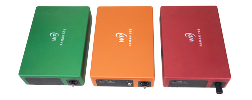
Configuration options include a choice of f/1.3 or f/1.8 input aperture, detector cooling level, slit size, and sample coupling. Models available include: 1) standalone spectrometers for modular Raman spectroscopy, 2) spectrometers with integrated excitation laser to reduce size, cabling and cost, 3) fully integrated Raman systems for maximum signal in the smallest footprint, and 4) OEM versions of each to reduce size, weight, and cost in volume. These options allow the user to balance signal, resolution, range, and form factor according to the unique needs of their application. Data collection and spectrometer control is included through the company’s own ENLIGHTEN™ operating software and software development kits for C/C++, C#, Python, LabVIEW, MATLAB, and other languages.

Designed to accelerate OEM product development

The X series was created using DFM (design for manufacturing) principles, resulting in a unified optomechanical design that serves the needs of both researchers and application-specific instrument manufacturers (OEMs). By leveraging the same robust, highly reproducible optical bench, users can complete proof-of-concept and method development with a fully housed unit, then transition directly to the corresponding OEM module for identical performance in volume, using the same matching libraries/chemometric models. This is a key advantage for aspiring university spin-offs and startups seeking to maximize velocity and conserve resources.

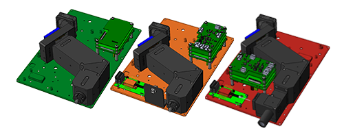
The X series’ ‘OEM by design’ approach ensures consistent performance at every stage, allowing OEMs to transition easily and confidently from research to product development faster, more efficiently, and with lower risk. All X series OEM modules, 532-1064 nm, are supported by a team of product and application specialists, open-source software, raw data access, and GitHub resources to simplify software development.

“The X series started with a question – What does the future of Raman look like?” says Dr. David Creasey, CEO of Wasatch Photonics. “Raman is well established in hazmat detection and pharma, and now it’s starting to take off in medical diagnostics and similar bioanalysis, pioneered by innovators who see its potential to provide very specific answers to complex questions. We created the X series to give them the sensitivity, reproducibility, and configurability they need to answer these questions with confidence, and to bring their solutions to market more rapidly.”

Wasatch Photonics’ new X series Raman spectrometers and systems are available for immediate sale in both laboratory and OEM modules. They can be configured for 532, 638, 785, 830, and 1064 nm Raman spectroscopy, supported by a full line of compatible user-configurable Raman probes and open-source software. The X series will be on exhibit throughout the coming year at SPIE BiOS/Photonics West, Spring SciX, and the FACSS SciX conferences. Read more about the X series here.

Want to talk with us about how the X series can enable your next research project or product development? Contact us

About Wasatch Photonics

Founded in 2002, Wasatch Photonics designs, manufactures and markets high-sensitivity compact spectrometers and systems designed specifically for Raman spectroscopy based on its own patented high efficiency volume phase holographic (VPH) gratings. The company also offers VPH gratings for pulse compression, astronomy, spectroscopy, spectral imaging, and optical coherence tomography (OCT), as well spectrometers and systems for OCT. Our high-performance VPH gratings, spectrometers, and systems can be found in research labs all over the world. We also work extensively with OEM partners spanning a diverse range of industries, including defense and security, chemical manufacturing, pharmaceutical, medical, energy, education, computer, and electronics sectors.


Sign up for updates

geophysics – How is the mass of the Earth determined?

0
geophysics – How is the mass of the Earth determined?

Note: I updated this answer to include a description of the historical techniques.

Historical Techniques

Newton developed his theory of gravitation primarily to explain the motions of the bodies that form the solar system. He also realized that while gravity makes the Earth orbit the Sun and the Moon orbit the Earth, it is also responsible for apples falling from trees. Everything attracts everything else, gravitationally. That suggested that one could in theory measure the gravitational attraction between a pair of small spheres. Newton himself realized this, but he didn’t think it was very practical. Certainly not two small spheres (Newton 1846):

Whence a sphere of one foot in diameter, and of a like nature to the
earth, would attract a small body placed near its surface with a force
20000000 times less than the earth would do if placed near its surface;
but so small a force could produce no sensible effect. If two such spheres
were distant but by 1 of an inch, they would not, even in spaces void of
resistance, come together by the force of their mutual attraction in less
than a month’s time; and less spheres will come together at a rate yet
slower, namely in the proportion of their diameters.

Maybe a mountain?

Nay, whole mountains will not be sufficient to produce any sensible effect. A mountain of an hemispherical figure, three miles high, and six broad, will not, by its attraction, draw the pendulum two minutes out of the true perpendicular :
and it is only in the great bodies of the planets that these forces are to be
perceived, …

Newton’s idea on the impracticality of such tiny measurements would turn out to be incorrect. Little did Newton know that the scientific revolution that he himself helped propel would quickly make such tiny measurements possible.

Weighing the Earth using mountains

The first attempt to “weigh the Earth” was made during the French geodesic mission to Peru by Pierre Bouguer, Charles Marie de La Condamine, and Louis Godin. Their primary mission was to determine the shape of the Earth. Did the Earth have an equatorial bulge, as predicted by Newton? (The French had sent a different team to Lapland to accomplish the same end.) Bouguer used the trip as an opportunity to test Newton’s suggestion that a mountain would deflect a plumb bob from surveyed normal. He chose Chimborazo as the subject mountain. Unfortunately, the measurements came up completely wrong. The plumb bob was deflected, but in the wrong direction. Bouguer measured a slight deflection away from the mountain (Beeson, webpage).

The next attempt was the Schiehallion experiment. While surveying the Mason-Dixon line, Charles Mason and Jeremiah Dixon found that occasionally their calibrations just couldn’t be made to agree with one another. The cause was that their plumb bobs occasionally deviated from surveyed normal. This discovery led to the Schiehallion experiment conducted by Nevil Maskelyne. Unlike Bouguer, Maskelyne did get a positive result, a deflection of 11.6 arc seconds, and in the right direction. The observed deflections led Maskelyne to conclude that the mean density of the Earth is 4.713 times that of water (von Zittel 1914).

It turns out that Newton’s idea of using a mountain is fundamentally flawed. Others tried to repeat these experiments using other mountains. Many measured a negative deflection, as did Bouguer. There’s a good reason for this. For the same reason that we only see a small part of an iceberg (the bulk is underwater), we only see a small part of a mountain. The bulk of the mountain is inside the Earth. A huge isolated mountain should make a plumb bob deviate away from the mountain.

Weighing the Earth using small masses

So if using mountains is dubious, what does that say about the dubiousness of using small masses that would take months to approach one another even if separated by mere inches?

This turned out to be a very good idea. Those small masses are controllable and their masses can be measured to a high degree of accuracy. There’s no need to wait until they collide. Simply measure the force they exert upon one another.

This idea was the basis for the Cavendish experiment (Cavendish 1798). Cavendish used two small and two large lead spheres. The two small spheres were hung from opposite ends of a horizontal wooden arm. The wooden arm in turn was suspended by a wire. The two large spheres were mounted on a separate device that he could turn to bring a large sphere very close to a small sphere. This close separation resulted in a gravitational force between the small and large spheres, which in turn caused the wire holding the wooden arm to twist. The torsion in the wire acted to counterbalance this gravitational force. Eventually the system settled to an equilibrium state. He measured the torsion by observing the angular deviation of the arm from its untwisted state. He calibrated this torsion by a different set of measurements. Finally, by weighing those lead spheres Cavendish was able to calculate the mean density of the Earth.

Note that Cavendish did not measure the universal gravitational constant G. There is no mention of a gravitational constant in Cavendish’s paper. The notion that Cavendish measured G is a bit of historical revisionism. The modern notation of Newton’s law of universal gravitation, $F=\frac {GMm}{r^2}$, simply did not exist in Cavendish’s time. It wasn’t until 75 years after Cavendish’s experiments that Newton’s law of universal gravitation was reformulated in terms of the gravitational constant G. Scientists of Newton’s and Cavendish’s times wrote in terms of proportionalities rather than using a constant of proportionality.

The very intent of Cavendish’s experiment was to “weigh” the Earth, and that is exactly what he did.

Modern Techniques

If the Earth was spherical, if there were no other perturbing effects such as gravitational acceleration toward the Moon and Sun, and if Newton’s theory of gravitation was correct, the period of a small satellite orbiting the Earth is given by Kepler’s third law: $\left( \frac T {2\pi} \right)^2 = \frac {a^3}{GM_E}$ . Here $T$ is the satellite’s period, $a$ is the satellite’s semi-major axis (orbital radius), $G$ is the universal gravitational constant, and $M_E$ is the mass of the Earth.

From this, it’s easy solve for the product $G M_E$ if the period $T$ and the orbital radius $a$ are known: $G M_E = \left( \frac {2\pi} T \right)^2 a^3$. To calculate the mass of the Earth, all one needs to do is divide by $G$. There’s a catch, though. If the product is $G M_E$ is known to a high degree of accuracy (and it is), dividing by $G$ will lose a lot of accuracy because the gravitational constant $G$ is only known to four decimal places of accuracy. This lack of knowledge of $G$ inherently plagues any precise measurement of the mass of the Earth.

I put a lot of caveats on this calculation:

  • The Earth isn’t spherical. The Earth is better modeled as an oblate spheroid. That equatorial bulge perturbs the orbits of satellites (as do deviations from the oblate spheroid model).
  • The Earth isn’t alone in the universe. Gravitation from the Moon and Sun (and the other planets) perturb the orbits of satellites. So does radiation from the Sun and from the Earth.
  • Newton’s theory of gravitation is only approximately correct. Einstein’s theory of general relativity provides a better model. Deviations between Newton’s and Einstein’s theories become observable given precise measurements over a long period of time.

These perturbations need to be taken into account, but the basic idea still stands: One can “weigh the Earth” by precisely observing a satellite for a long period of time. What’s needed is a satellite specially suited to that purpose. Here it is:

geophysics – How is the mass of the Earth determined?

This is LAGEOS-1, launched in 1976. An identical twin, LAGEOS-2, was deployed in 1992. These are extremely simple satellites. They have no sensors, no effectors, no communications equipment, no electronics. They are completely passive satellites. They are just solid brass balls 60 cm in diameter, covered with retroreflectors.

Instead, of having the satellite make measurements, people on the ground aim lasers at the satellites. That the satellites are covered with retroreflectors means some of the laser light that hits a satellite will be reflected back to the source. Precisely timing the delay between the emission and the reception of the reflected light gives a precise measure of the distance to the satellite. Precisely measuring the frequency change between the transmitted signal and the return signal gives a precise measure of the rate at which the distance is changing.

By accumulating these measurements over time, scientists can very precisely determine these satellites orbits, and from that they can “weigh the Earth”. The current estimate of the product $G M_E$ is $G M_E=398600.4418 \pm 0.0009 \ \text{km}^3/\text{s}^2$. (NIMA 2000). That tiny error means this is accurate to 8.6 decimal places. Almost all of the error in the mass of the Earth is going to come from the uncertainty in $G$.

References

M. Beeson, “Bouguer fails to weigh the Earth” (webpage)

H. Cavendish, “Experiments to determine the Density of the Earth,” Phil. Trans. R. Soc. London, 88 (1798) 469-526

I. Newton (translated by A. Motte), Principia, The System of the World (1846)

NIMA Technical Report TR8350.2, “Department of Defense World Geodetic System 1984, Its Definition and Relationships With Local Geodetic Systems”, Third Edition, January 2000

K. von Zittel (translated by M. Ogilvie-Gordon), “History of Geology and Palæontology to the End of the Nineteenth Century,” (1914)

User talk:Aliumair435: Difference between revisions

0
User talk:Aliumair435: Difference between revisions


Line 37: Line 37:

Users may edit the article during the discussion, including to improve the article to address concerns raised in the discussion. However, do not remove the article-for-deletion notice from the top of the article until the discussion has finished.<!– Template:Afd notice –></div> [[User:Whpq|Whpq]] ([[User talk:Whpq|talk]]) 03:48, 14 October 2024 (UTC)

Users may edit the article during the discussion, including to improve the article to address concerns raised in the discussion. However, do not remove the article-for-deletion notice from the top of the article until the discussion has finished.<!– Template:Afd notice –></div> [[User:Whpq|Whpq]] ([[User talk:Whpq|talk]]) 03:48, 14 October 2024 (UTC)

== October 2024 ==

[[File:Information.svg|25px|alt=Information icon]] Welcome to Wikipedia. Please do not remove [[Template:Article for deletion|Articles for deletion notices]] from articles, or remove other people’s comments in [[Wikipedia:Articles for deletion|Articles for deletion debates]], as you did with [[:Jason Hennessey]]. Otherwise, it may be difficult to create [[Wikipedia:Consensus|consensus]]. If you oppose the deletion of an article, please [[Wikipedia:Guide to deletion|comment]] at the respective page instead. Thank you.<!– Template:uw-afd1 –> [[User:Sjö|Sjö]] ([[User talk:Sjö|talk]]) 10:37, 17 October 2024 (UTC)

Thanks for your contributions to Jason Hennessey. Unfortunately, I do not think it is ready for publishing at this time because it is promotional and reads like an advertisement.
I have converted your article to a draft which you can improve, undisturbed for a while.

Please see more information at Help:Unreviewed new page.
When the article is ready for publication, please click on the “Submit your draft for review!” button at the top of the page OR move the page back. 🔥YesI’mOnFire🔥(ContainThisEmber?) 12:57, 28 September 2024 (UTC)[reply]

Thank you for reviewing my article. I would appreciate your guidance in preparing it for publication. Specifically, could you identify any instances of promotional or advertising language? Additionally, please advise on any content that should be removed.
Thank you for your assistance. Aliumair435 (talk) 16:10, 28 September 2024 (UTC)[reply]

User talk:Aliumair435: Difference between revisions Hello, Aliumair435. We welcome your contributions, but if you have an external relationship with the people, places or things you have written about on Wikipedia, you may have a conflict of interest (COI). Editors with a conflict of interest may be unduly influenced by their connection to the topic. See the conflict of interest guideline and FAQ for article subjects for more information. We ask that you:

In addition, you are required by the Wikimedia Foundation’s terms of use to disclose your employer, client, and affiliation with respect to any contribution which forms all or part of work for which you receive, or expect to receive, compensation. See Wikipedia:Paid-contribution disclosure.

Also, editing for the purpose of advertising, publicizing, or promoting anyone or anything is not permitted. Thank you. 🔥YesI’mOnFire🔥(ContainThisEmber?) 12:58, 28 September 2024 (UTC)[reply]

A tag has been placed on Jason Hennessey requesting that it be speedily deleted from Wikipedia. This has been done under section A7 of the criteria for speedy deletion, because the article appears to be about a real person or group of people that does not credibly indicate how or why the subject is important or significant: that is, why an article about that subject should be included in an encyclopedia. Under the criteria for speedy deletion, such articles may be deleted at any time. Please read more about what is generally accepted as notable.

If you think this page should not be deleted for this reason, you may contest the nomination by visiting the page and clicking the button labelled “Contest this speedy deletion”. This will give you the opportunity to explain why you believe the page should not be deleted. However, be aware that once a page is tagged for speedy deletion, it may be deleted without delay. Please do not remove the speedy deletion tag from the page yourself, but do not hesitate to add information in line with Wikipedia’s policies and guidelines. If the page is deleted, and you wish to retrieve the deleted material for future reference or improvement, then please contact the deleting administrator. Widoreu (talk) 20:34, 10 October 2024 (UTC)[reply]

A discussion is taking place as to whether the article Jason Hennessey is suitable for inclusion in Wikipedia according to Wikipedia’s policies and guidelines or whether it should be deleted.

The article will be discussed at Wikipedia:Articles for deletion/Jason Hennessey until a consensus is reached, and anyone, including you, is welcome to contribute to the discussion. The nomination will explain the policies and guidelines which are of concern. The discussion focuses on high-quality evidence and our policies and guidelines.

Users may edit the article during the discussion, including to improve the article to address concerns raised in the discussion. However, do not remove the article-for-deletion notice from the top of the article until the discussion has finished.

Whpq (talk) 03:48, 14 October 2024 (UTC)[reply]

User talk:Aliumair435: Difference between revisions Welcome to Wikipedia. Please do not remove Articles for deletion notices from articles, or remove other people’s comments in Articles for deletion debates, as you did with Jason Hennessey. Otherwise, it may be difficult to create consensus. If you oppose the deletion of an article, please comment at the respective page instead. Thank you. Sjö (talk) 10:37, 17 October 2024 (UTC)[reply]